

In its most common version, muon imaging is intrinsically a 2D technique: the resulting density map is indeed integrated along the observation direction. However, a 3D map can be obtained by combining several projections, like for medical imaging. But in the muon case, the number of projections is dramatically reduced because of the required acquisition time. A 3D algorithm has been recently developed using the Irfu TomoMu setup, within a collaboration between Florence University and Irfu. The 3D structure of the test object has been reconstructed from only 3 points of view, thanks to the high precision of the instrument. This technique will soon be extended to more applications, from reactor dismantling to civil engineering or mining exploration.
Introduction
Muon imaging is a non-destructive, highly penetrating technique making use of cosmic muons to probe the inside of objects (see picture on the right). From its very first application in 1955, this technique has benefitted from outstanding progress both on hardware (particle detectors) and software (reconstruction algorithms) aspects. In 2003, a team from Los Alamos has developed the first 3D muon imaging using scattering of muons in matter, by sandwiching relatively small objects with particle detectors. In 2015, the 3D structure of a volcano was inferred using several muon telescopes of limited resolution. In 2017 a measurement of underground cavities of the Bourbon Gallery in Naples gave hints on the presence of an unknown void later confirmed and precisely localized by two other measurements. In the same year, the extensive use of very precise particle detectors managed to reveal and localize a large cavity deep inside the Khufu’s pyramid in Giza. High-definition muon telescopes from Irfu performed at this occasion the very first detection of deep structures of a pyramid from the outside. It then became clear that precise 3D muon tomography was at hand for any size of objects by combining high-definition 2D projections and a robust 3D algorithm applicable with a limited number of such projections.
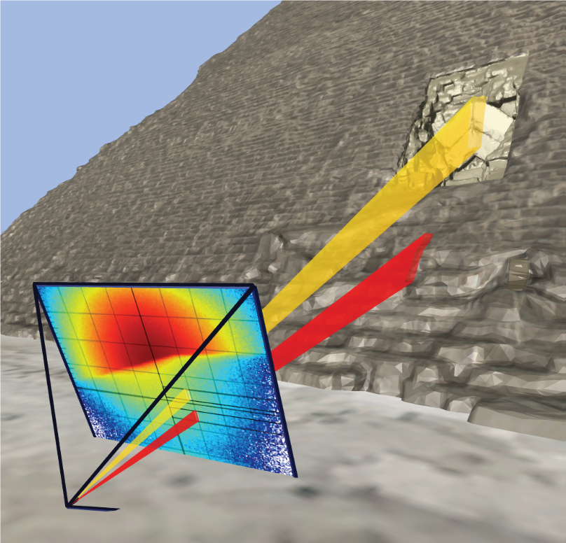
A 2D muography of a 3D structure (Khufu’s Pyramid).
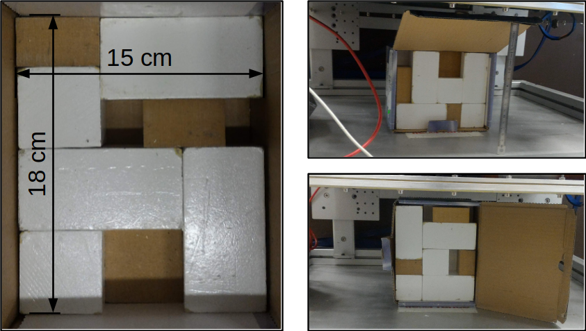
(Left): the first Lead layer of the target. (Right): two of the three setups with the target inside TomoMu.
Experimental setup
We decided here to use the absorption muography for the 2D imaging technique. Absorption muography is experimentally different from the usual transmission method employed for imaging large targets but both techniques measure the so-called opacity X, i.e. the density integral along a line of sight:
X(θ,φ)=∫ρdL
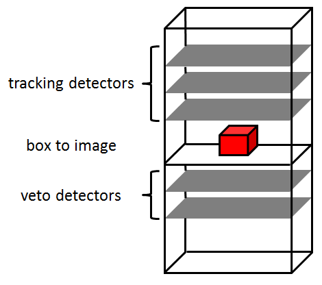
The target to image was made of Lead bricks arranged in a box of around 15 cm per side (see picture on the left). Absorption data were acquired using the TomoMu instrument with three different orientations of the target inside it. For these measurements, TomoMu consisted of five Micromegas detectors, three above the target to reconstruct the track and two below acting as a veto to identify the absorbed tracks (see picture below).
3D reconstruction (inverse problem)
A general way to perform the tomography consists in dividing the volume around the target in a matrix of 3D pixels called Voxels. For this study, cubic Voxels with 1-3 cm per side were used, resulting in a total number of Voxels J around 1-6 103. The information on the opacity provided by the muon absorption probability is gathered in objects called Rays that could be geometrically defined as binned directions (both in space and in angle). For this analysis, the number of available Rays I was about 3 103.
Each Ray has to be calibrated to convert the muon absorption probability into an opacity measurement. Three calibration measurements were thus acquired with uniform layers of lead (0 cm, 5 cm and 10 cm). To reconstruct the 3D distribution of density we then have to solve the following system of equations:
Xi=Σj Lijρj
where:
- Xi is the opacity measurement for the Ray i (with i ranging from 1 to I);
- ρj is the density of Voxel j (with j ranging from 1 to J);
- Lij is the intersection length between the Voxel j and the Ray i.
ART and SART algorithms
The Algebraic Reconstruction Technique (ART) is an iterative algorithm that allows solving a system of linear equations with a large number of both equations and unknowns. The vector of J unknowns (here the density of each Voxel) can be represented as a point in a J dimensional space while the I equations (each corresponding to an opacity measurement) can be represented as I hyperplanes in the same space. Following the ART algorithm we can solve the problem by sequentially projecting at each iteration the point on each hyperplane. In the Simultaneous ART (SART) algorithm a single iteration is obtained by averaging the projections for all the hyperplanes. In addition to a faster convergence, the SART version easily takes into account the opacity error for each Ray-hyperplane by using a weighted average of the projections.
Results and future developments
After 10 iterations with the SART algorithm (which took only 0.4 second!) we obtained a good agreement between the reconstructed target and the real one: the shape of the target is well reproduced and the density values are compatible with that of Lead (see picture on the right).
Some additional studies are now planned to better define and understand the stopping criterion, in particular the stability of the results as a function of the relative size of the Voxels and of the Rays. This method will also be tested soon with larger objects, like mines, reactors and pyramids. In several cases, the implementation of a DART algorithm (Discrete ART) can further constrain the solution by limiting the densities to a discrete set of values (e.g. rock or air).
Further reading:
ART & SART : A. C. Kak, M. Slaney and G. Wang, "Principles of computerized tomographic imaging." Medical Physics 29.1 (2002): 107-107. Chapter 7
DART : K. J. Batenburg and J. Sijbers, "DART: a practical reconstruction algorithm for discrete tomography", IEEE Transactions on Image Processing (2011), 20.9: 2542-2553.
Contacts:
G. Baccani (PhD student from Florence University and main author of this work performed during a 3 month stay at Saclay, )
S. Procureur (CEA/Irfu)
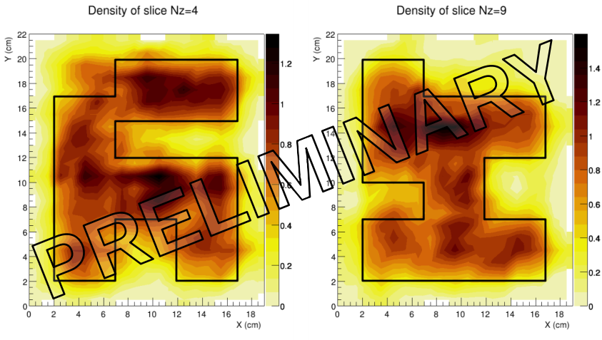
Horizontal slices at the median planes of the two layers of the target. The black line is the boundary of the Lead bricks. The density values are normalized to the Lead one.
• Innovation for detection systems › Achievements in response to societal challenges › MPGD Activities Constituants élémentaires et symétries fondamentales Détection des rayonnements
• Institut de recherche sur les lois fondamentales de l'Univers (Irfu) • Le Département d'Électronique des Détecteurs et d'Informatique pour la Physique (DEDIP) • Le Département de Physique des Particules (DPhP) • Le Département de Physique Nucléaire (DPhN)
