

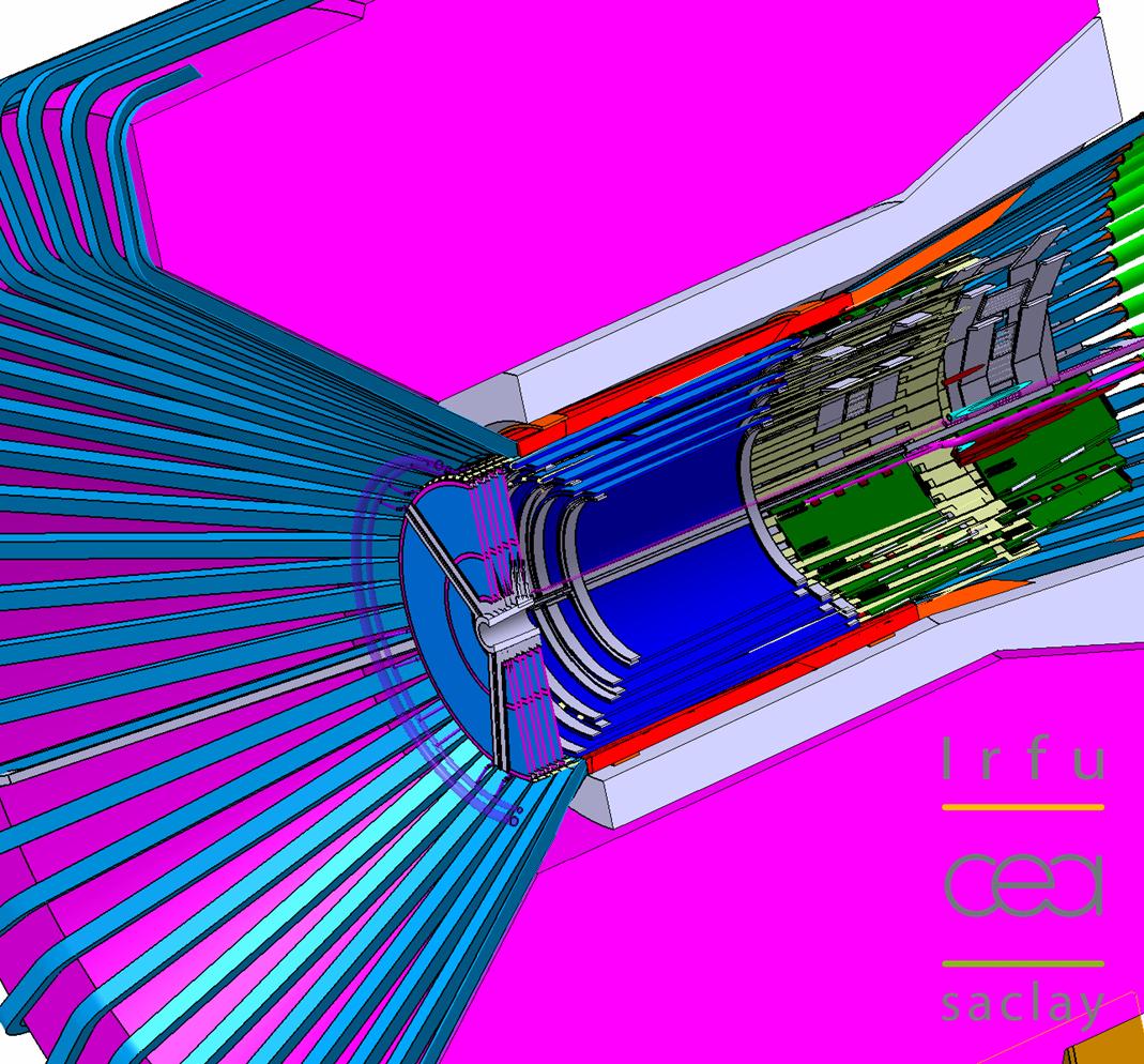
Investigation of the installation of a micromegas bulk layer for the central trajectories (in blue) in the forthcoming new magnet (in pink) for CLAS12.
A joint team from the Nuclear Physics Department (SPhN), the Electronics, Detectors and Computing Department (Sedi) and the Systems Engineering Department (SIS) of IRFU, have recently designed and tested a 2nd generation prototype of Micromegas gaseous detector in the CLAS-DVCS solenoid* at Jefferson Laboratory (Virginia, USA). For the first time ever, it has been shown that a Micromegas detector can operate in a very unfavourable magnetic environment (4.2 T parallel to the strips of the detector). The measurements performed during these tests agree with the simulations, and constitute an important step towards the possible implementation of these detectors in the future Central Tracker of CLAS12 (an upgrade of the CLAS spectrometer due to the energy increase of Jefferson Lab at 12 GeV in 2014).

Fig. 1: Measurement principle: The UV laser is attenuated and focused, via a set of mirrors and lenses, on the drift electrode of the detector. The created electrons drift in the conversion space with a Lorentz angle, θ. The ones coming from the micromesh provide the laser position, and the distance between the two signals thus gives a measurement of θ.
In view of the energy increase of the electron accelerator at Jefferson Laboratory, the CLAS spectrometer should be significantly upgraded for 2014. The project, named CLAS12, plans in particular the construction a Central Tracker, installed in a 5 T solenoid, and dedicated to the detection of protons and pions of average momentum (between 0.2 and 1.5 GeV/c).
Initially, this tracker was supposed to be composed of silicon detectors, coming from an American-Russian collaboration, having a large total surface area (0.8 m²) and consisting of 35,000 electronic channels. However, in order to improve the angular resolution, whilst reducing the quantity of material and the cost of such an equipment, the CLAS group from SPhN has suggested to replace 80% of these silicons with Micromegas gaseous detectors. This suggestion was made following the R&D performed at Sédi on the next generation of Micromegas, known as "bulks". Simulations, based on the Garfield and Magboltz programs, have confirmed the potential of such a mixed setup in terms of spatial and angular resolutions. There is, however, a major difficulty related to the use of gaseous detectors in a high magnetic field. Indeed, the electrons, created by the passage of a charged particle in the detector, drift with a high Lorentz angle, with respect to the direction of the electric field. In standard conditions, this angle is around 75°, and the detector is unusable. Simulations have shown that it could be possible to reduce this angle below 20°, thanks to a judicious choice of gas and by increasing the drift field of the detector, that would have a cost in terms of micromesh transparency. With such an angle, the detector could reconstruct tracks with an efficiency greater than 95%.
Micromegas prototypes have been produced at CERN and tested at Sédi, as well as an experimental setup for the measurement of the Lorentz angles. In this setup (Figure 1) a UV laser is focused on the aluminised Mylar drift electrode of the detector, and simulates the passage of a particle in the detector by creating a large number of electrons from aluminium atoms. These electrons then drift in the gaseous volume of the detector and, after amplification, are collected on the strips connected to electronics developed for the T2K (AFTER) experiment. An essential feature of this setup is that the laser is also able to create electrons from the detector's micromesh.
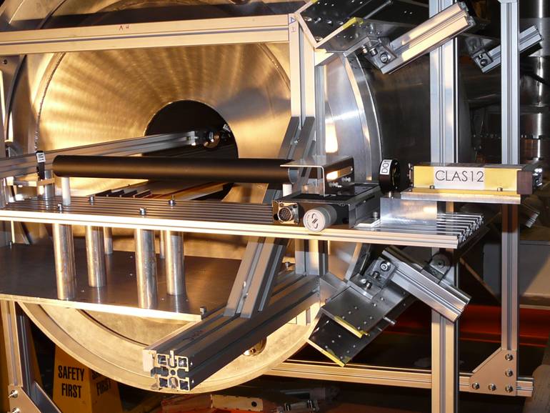
Fig. 2: photograph of the platform mounted in the CLAS-DVCS magnet in Hall B.
In the presence of a magnetic field the signals due to drift electrons and those due to electrons from the micromesh thus give rise to two separate peaks on the strips, and the position difference between these peaks provides a direct measurement of the Lorentz angle seen by the electrons in the drift space. A first set of measurements of the Lorentz angles was performed at Saclay, where a hot dipole from SACM allowed to collect data up to 1.5 T on a small Micromegas detector. The agreement with the simulation was found to be fairly good, and these tests have therefore validated both the measurement setup as well as the relevance of the simulation in intermediate magnetic fields.
The same setup has been installed in real conditions, inside the CLAS solenoid magnet in the Hall B of the Jefferson Laboratory (Figure 2). The used detector had an active surface area of 53 x 12 cm² on a 100 microns thick PCB, with a drift electrode of aluminised mylar located several millimeters above the micromesh. The measurements were performed in a 10% argon-isobutane mixture, in a field ramped from 0 to 4.2 T, and for various values of drift electric field (Figure 3).
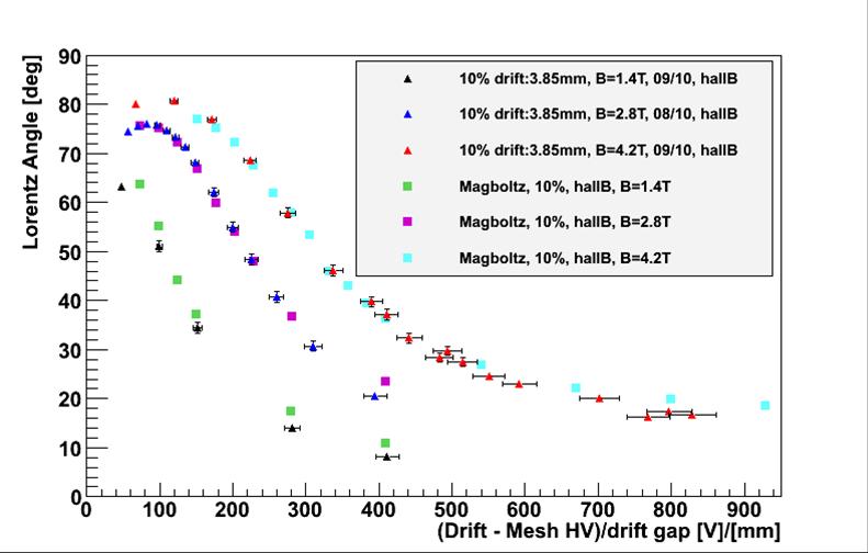
Fig. 3: Comparison of the measured Lorentz angles with the simulation, for various values of the magnetic field, as a function of the electric field in the drift gap of the detector
It was noticed that the detector could be operated up to Lorentz angles of 16° at 4.2 T, i.e. close to the working point required by the simulation (20° at 5 T). It was also noticed that this simulation reproduced the measured Lorentz angles in a very satisfactory way, particularly at high magnetic fields - the simulation programs for electron drift in gas have, moreover, never previously been validated at such high fields. This agreement helps to make the other predictions from the simulation more reliable, and in particular the improvement of the spatial resolution of the Central Tracker with a mixed setup of silicons and Micromegas. This first validation of the simulation is a significant step towards the decision on whether or not to use Micromegas for CLAS12, a decision that will be taken in a couple of months, during a project review at Jefferson Laboratory.
Between now and then, several additional tests will be carried out in order to complete the validation of the simulation, such as measurement of the spatial resolution of the detector, its particle detection efficiency for minimum ionizing particles, and also the sparking rate in beam conditions. Moreover, the previously used 1.5 T test bench will allow systematic studies to be carried out on small detectors such as, for example, the influence of the gas.
Finally, the results presented here will shortly be published.
Sébastien PROCUREUR (SPhN)
Stephan AUNE (Sédi)
• Structure of nuclear matter › Quarks and gluons hadron structure The ultimate constituents of matter
• Institute of Research into the Fundamental Laws of the Universe • Accelerators, Cryogenics and Magnetism Division (DACM) • The Electronics, Detectors and Computing Division • The Nuclear Physics Division • The Systems Engineering Division
• CLAS12
![]() PHoCEA DSM 2024 - Tous droits réservés - Mentions légales - Ce site utilise Twitter Bootstrap
PHoCEA DSM 2024 - Tous droits réservés - Mentions légales - Ce site utilise Twitter Bootstrap
Dernière mise à jour : Feb 19th, 2024

