


Figure 1: NFS experimental area scheme (converter and time-of-flight (TOF) rooms)
NFS (Neutrons For Science) is an experimental area of the Spiral2 facility (Ganil, France) that will provide high intensity neutron beams for energies ranging from 0.5 to 40 MeV. The neutrons will be created by collision of Spiral2 charged particles with carbon, beryllium or lithium targets, thanks to a key element of NFS, the converter. The design of this one is a real challenge because it has to withstand a high power deposited by Spiral2's intense beams. In this context, Irfu has designed and built a converter able to support a power of 2 kW. NFS neutron beams will provide information in an unexplored energy domain. Fundamental physics, nuclear reaction modelling and nuclear databases will thus benefit from a unique tool.
NFS (Fig. 1) will use the high-intensity particle beams of Linag Spiral2 to produce neutron beams via the 7Li(p,n)7Be reaction or deuteron breakup on a beryllium or carbon target. Two types of beams will then be available: mono-energy beams and white beams (continuous energy spectrum). Intensities in the order of 106 neutrons/cm2/s (5 m from the converter) for energies from a few hundred of keV to 40 MeV are expected, offering new experimental opportunities. For example, an Irfu team is currently developing a spectrometer, called Falstaff, which, once installed at NFS, will study actinide fission.
For the NFS project, Irfu developed a robotic system called a "converter set" (Fig. 2) to produce neutron beams with white spectra. The assembly makes it possible to load a carbon or beryllium target of variable thickness, then to control its rotation and to monitor its integrity under 2 kW of deuterons. Remote management ensures the loading and unloading of the target inside the reaction chamber until it is placed in storage. This project covers a wide range of Irfu skills: project management, neutron calculations, radiation protection, thermal calculations, mechanical design, mechanical engineering, electrical engineering, automation, alignment, set up and fitting.
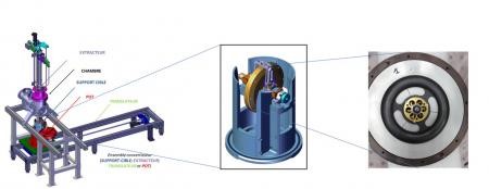
Figure 2: Scheme of the converter assembly (left) and enlargement of the target holder (middle) and target (right)
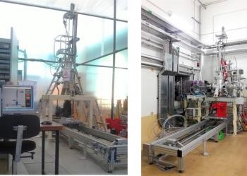
Figure 3: picture of the convertor assembly tested in Irfu (left) and installed in NFS (right) at Ganil.
The mechanical design consist of four equipments that meet both the radiological access and thermal operating constraints of the converter:
- the rotating target set ensuring rotation, balancing and heat exchange of the converter (Be or C targets of different thicknesses);
- the extractor set, an "arm" allowing the gripping and docking of the target set to the vacuum chamber during the loading phase, then the positioning of the target set in its lead pot at the end of the irradiation phase;
- the lead pot providing biological containment protection;
- the table set for the translation of the lead pot on a trolley over ~2 m, and ensuring the positioning of the target set perfectly below the chamber and the extractor, before and after irradiation.
Thermal and thermomechanical calculations were at the core of the design choices. A thermal simulation model was developed, taking into account the conduction and radiation phenomena that occur between the parts of the target set and the extractor. Considering the high power output, 2 kW maximum, the temperature of the target, depending on its material, can reach 940°C. The size, as well as the rotation speed of the target (~2000 rpm), were chosen in order to manage the power density deposited by the beam by distributing it over a ring of the disk. The heat exchange takes place over several stages: by radiation from the rotating target towards "cold" surfaces, then by conduction through an elastic contact to the extractor itself cooled down by convection thanks to a water circulation at 12°C. In addition, the target was thermally insulated from its support by ceramic components, thus limiting the transfer of power to the motor (temperature < 100°C). The thermomechanical stresses that appear by expansion and rotation thus remain under control to ensure the integrity of the target.
Electrotechnical/Instrumentation: Monitoring target rotation is crucial. It is ensured by two distinct instrumentation lines in order to meet safety requirements because the target is an EPS (Element Participating in Safety). A high reactivity of detection (in 100 ms) of speed defects is necessary in order to maintain the integrity of the target (beam switch off < 250 ms). The target speed is regulated to ± 0.2% and the fault activation to ± 10%. The very harsh environment has been a technological challenge for the selected components (radiation, vacuum, high temperature, miniaturization, maintenance, failure rate...). This environment has led to the robotization of all the actions and manipulations of the target, from its containment to its use.
Control-command: One of the main goals of the control-command system is to drive the converter when the experiment room is locked and prohibited access. This ensures that an irradiated target is either positioned in the reaction chamber rotating in the axis of the beam, or is confined to a standstill in its lead pot. This system also provides the operator interface for target loading and unloading requests.
The control command system chosen is based on tools standardised by Irfu. A programmable controller manages all the motorized axes with accuracy (0.1 mm over 2 m) and in a reliable and repetitive way. The Muscade® supervision software provides the human-machine interface. Indeed, it implements an industrial programmable logic controller (200 parameters to be managed per axis) which is coupled to variable speed drives. The system interfaces with the Ganil PLCs in order to take into account the environmental constraints of the experiment.
The converter assembly was mounted, fitted and tested at Irfu and then in the NFS room at Ganil. Photos of the set are shown in Figure 3.
The different skills present at Irfu have been integrated in order to produce the NFS converter set. Delivery to Ganil took place at the end of March 2018. The converter is now assembled, fitted and tested since June 2018. The Spiral2 Linag beam is expected in the NFS converter room by 2020. During the increase in power, the measurements of the temperature sensors will be compared with the expectations of the thermal calculations in order to allow their validation.
Find out more about the work of the Irfu teams through this video:
Contacts: D. Doré, J.-C. Toussaint
• Structure of nuclear matter › Nuclear reaction dynamics
• Institute of Research into the Fundamental Laws of the Universe • The Electronics, Detectors and Computing Division • The Nuclear Physics Division
![]() PHoCEA DSM 2024 - Tous droits réservés - Mentions légales - Ce site utilise Twitter Bootstrap
PHoCEA DSM 2024 - Tous droits réservés - Mentions légales - Ce site utilise Twitter Bootstrap
Dernière mise à jour : Feb 19th, 2024

