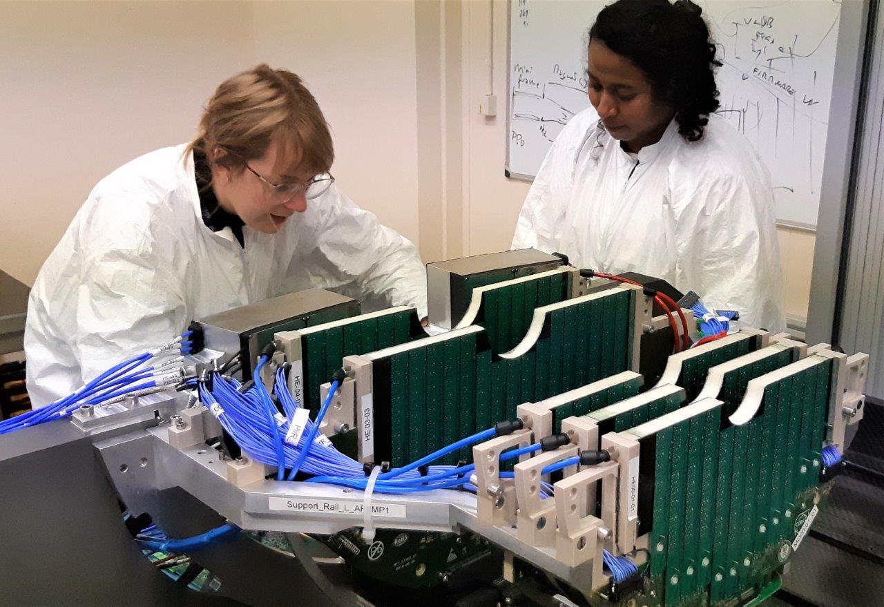
Figure 1: Laboratory commissioning of the fully assembled MFT detector (© Collaboration MFT)
After more than four years of research and development, design and manufacturing work, the MFT (Muon Forward Tracker), a new detector that will equip the ALICE experiment at the LHC, has seen its construction finalized and is currently under commissioning at CERN. In order to limit as far as possible the amount of material crossed by the particles, the conception of this detector has required the development of many innovative techniques and procedures, particularly in the integration of silicon sensors on flexible hybrid circuits called ladders, for which Irfu was responsible within the project. It took two years to manufacture the 500 ladders of the MFT, and a very long sequence of operations was the subject of numerous studies under the responsibility of the Irfu Antenna team at CERN. The production of these ladders has just been successfully completed and it is therefore time to make a short assessment
More than 1,000 silicon sensors, corresponding to an area of half a square meter, assembled into almost 500 integrated circuits, glued on both sides of 10 half-disks, all mounted in a 4 meter long barrel, which has to be positioned inside the ALICE experiment to the nearest tenth of a millimeter. This was the challenge for the MFT detector (figure 1), designed as part of the upgrades of the ALICE experiment at the LHC to better understand a very exotic state of matter called the quark-gluon plasma. For more than five years, Irfu and a dozen research institutes in Europe, Asia and South America have been working to build this high-precision trajectograph, which will be placed in front of the hadron absorber of the ALICE experiment (figure 2). Coupled with the current muon spectrometer, it will make it possible to detect pairs of muons from particle collisions (protons and lead ions) with a spatial resolution of 5 micrometers and to reconstruct the vertex from which these pairs of muons originate.
The basic element of the MFT detector is called a ladder: it is a hybrid integrated system consisting of a Flexible Printed Circuit (FPC) on which silicon sensors (chips) are glued and interconnected. Since they are then glued onto disks of increasing diameter, their length is variable, from 2 to 5 chips each.
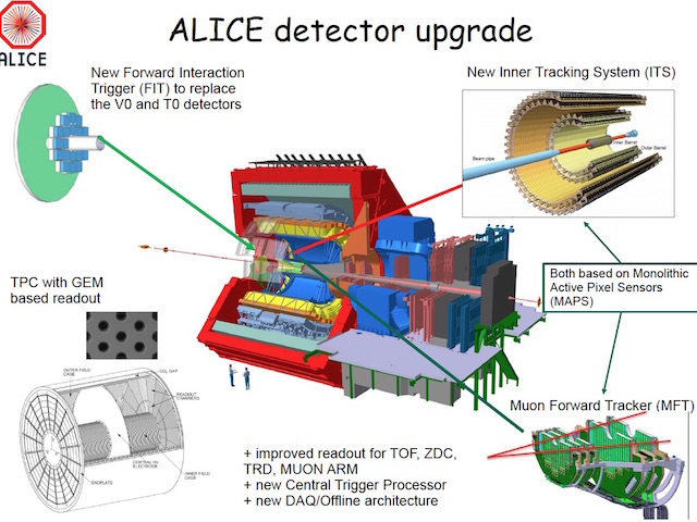
Figure 2 : Diagram of Alice detector upgrade
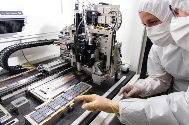
Figure 3 : Digital assembly machine (ALICIA) located in a clean room at CERN (© Ph. Stroppa/CEA)
Making a ladder: the recipe for success
As in any cooking recipe, before starting to cook, the ingredients must be prepared. In this case there are only two: chips and flexible printed circuits.
The MFT sensor, called ALPIDE, was designed by an international team led by CERN, of which IRFU was a member. It is a thin silicon wafer with a surface area of 4.5 cm², 50 µm thick, fragile as glass, into which half a million pixels and their readout electronics have been etched. Manufactured by a specialized foundry in Israel, we receive these chips in the form of a wafer in which 46 sensors are pre-cut by laser in a Korean company. The delicate picking operation then begins in the clean room: the aim is to separate each chip from the wafer and place it delicately and in a defined order in a dedicated box. A chip measures 30 mm by 15 mm, each one has its own identification and undergoes a thorough visual inspection using a binocular magnifying glass in order to remove any dust or silicon debris. Once they are ready in their tray, the performance of each chip is tested using a probe card that deploys thin needles connecting to the 63 metal pads on the chip surface and performs a multitude of electrical and electronic tests to qualify it.
The FPC is a flexible polyamide printed circuit board with two layers of aluminum on either side. Designed by a team from IN2P3, it is equipped on one side with slots for placing the sensors and a 70-pin connector for powering the chips and transmitting signals at very high speed (1.2 Gb per second), and on the other side with microelectronic components (resistors and capacitors) that decouple the power supply (analog and digital) from the sensors and adapt the impedance of the data lines. Each FPC has a constant width of 16.7 mm while its length can vary from 99.65 mm to 190.10 mm depending on the number of sensors present on the ladder. The FPCs are manufactured at CERN (the only laboratory in the world where this type of production is possible) from an aluminum foil (to reduce the material budget) lithographed on a polyamide substrate, pre-cut and laser-drilled in Italy, then detached and inspected at CERN, and finally sent to a specialized company in the Nantes region for cabling and connector installation. Once cabled, the FPCs are again thoroughly inspected in the MFT laboratory of the Irfu Antenna at CERN to check the quality of the welds, the correct position of the components, and to remove any foreign substances. The FPC is now ready to enter the clean room, where a series of deep cleanings are carried out using ultrasonic baths based on alcohol, water with industrial detergent and demineralized water. The FPCs are then dried and re-inspected to detect any metallization defects, flatness and size of the interconnection pads to the sensors, as well as any possible contamination. Finally, a semi-adhesive mask is placed over each CPF to protect it during the gluing steps.
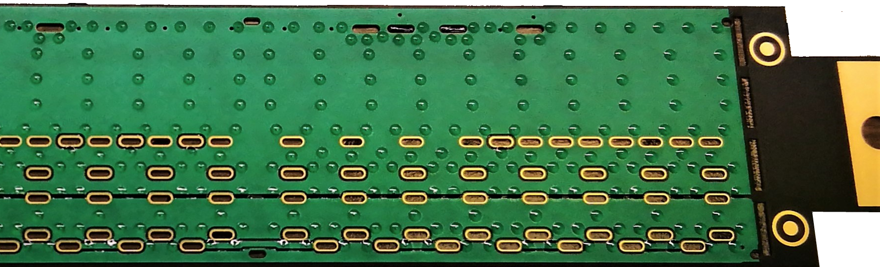
Figure 4 : Glue dots with a diameter of 0.7 mm deposited on the FPC by screen printing (© Collaboration MFT)
So the ingredients are ready and the recipe (finally... the assembly of the ladder) can begin. This takes place in a clean room using a three-axis digital machine, called ALICIA (ALICE Integrated Circuit Inspection and Assembly machine), which positions the chips with a precision of 5 µm on a specially machined stainless steel support with a lattice of very small holes which, by suction, keep the chips adhering to the support (figure 3). At the same time, the FPC is positioned on a suction support which also keeps it perfectly flat and in a very precise position. Small dots of Araldite-type bi-component glue are applied to the FPC by scraping the glue on a stainless-steel stencil previously positioned on the FPC and provided with conical holes. The stencil is immediately removed to reveal pretty spots of glue skillfully distributed to avoid overflowing into the holes, called vias, which will be used to interconnect the FPC with the chips (figure 4).
Without waiting, the FPC held by the vacuum on its support is positioned opposite the chips with the help of precision centering pins. The weight of the FPC carrier allows sufficient pressure and a wedge between the FPC and the chips guarantees a final glue thickness of 50 µm. The assembly is left in ALICIA for at least 4 hours so that the glue can begin to cure. A few days later, once the glue is well cured (figure 5).
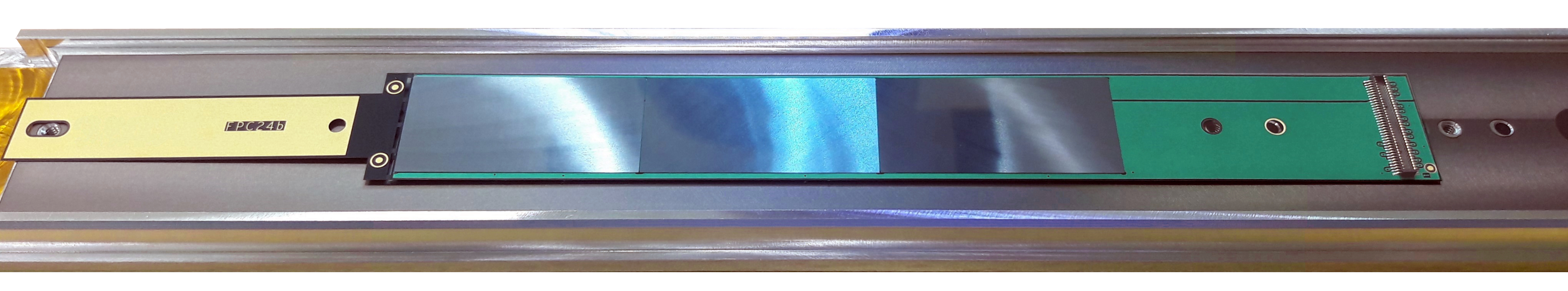
Figure 5 : Back side of a ladder equipped with 4 chips. On the right side of the FPC you can see the 70-pin connector (© collaboration MFT)
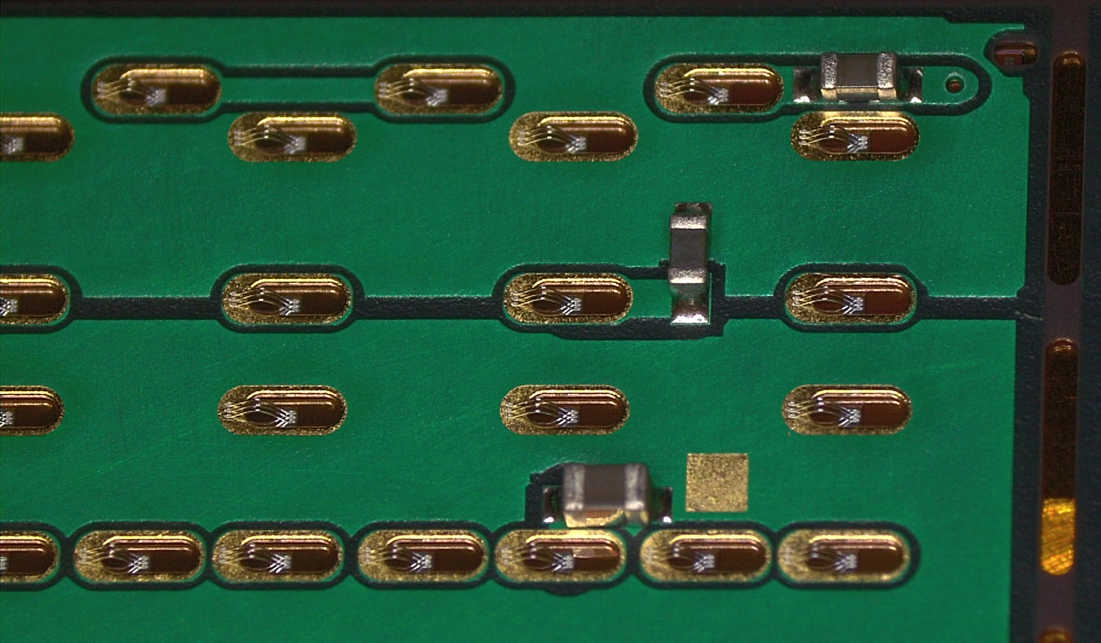
Figure 6 : 3 micro wires per via, ultrasonically fixed on one side to a Nickel/Gold metallized pad of the FPC and on the other side to a pad of the chip (© collaboration MFT)
And after a careful inspection of the assembly, the connection between the FPC and the chips is made by ultrasonic micro-wire bonding on the metallized pads of the FPC. Each micro-interconnection consists of 3 wires of 25 µm in diameter that pass through the vias of the FPC to be connected to the 74 pads on the surface of the sensors (figure 6). The assembly of the ladder is then complete and a final visual inspection verifies the quality of the interconnections.
Throughout these procedures, a very thorough quality control is ensured: temperature and humidity are monitored, all operations and photos taken during assembly are recorded in tracking sheets, and each ladder has a unique identity number allowing it to be traced exactly to all stages of its production.
After manufacturing, the qualification
Once the ladder is assembled, it is transferred to the MFT laboratory at the Irfu Antenna at CERN, where it undergoes a battery of tests to qualify its performance. In the laboratory, two test benches allow each ladder to be tested from an electrical and functional point of view. First of all, the ladder is gradually powered with analog and digital voltage and its power consumption is checked (this is called the "smoke test": if there is no smoke, it's actually better!). Then, the ladder is connected to an acquisition system developed specifically for the project (and which had been used to perform the first test under the beam of an MFT disk, see the associated Highlight) which allows its functionality to be tested in terms of electronic noise, number of dead or abnormal pixels, transmission speed of the digitized data (figure 7). Each test is associated with a qualification grade which is a function of the performance measured against the expected specifications. At the end of these tests, the ladder is qualified according to three grades:
Finally, as in any recipe, there are failures and sometimes a ladder does not pass the tests, for various reasons that can be a damage of the chips, a defect of the FPC or a bad handling. In this case it is qualified as "non-compliant" and set aside.
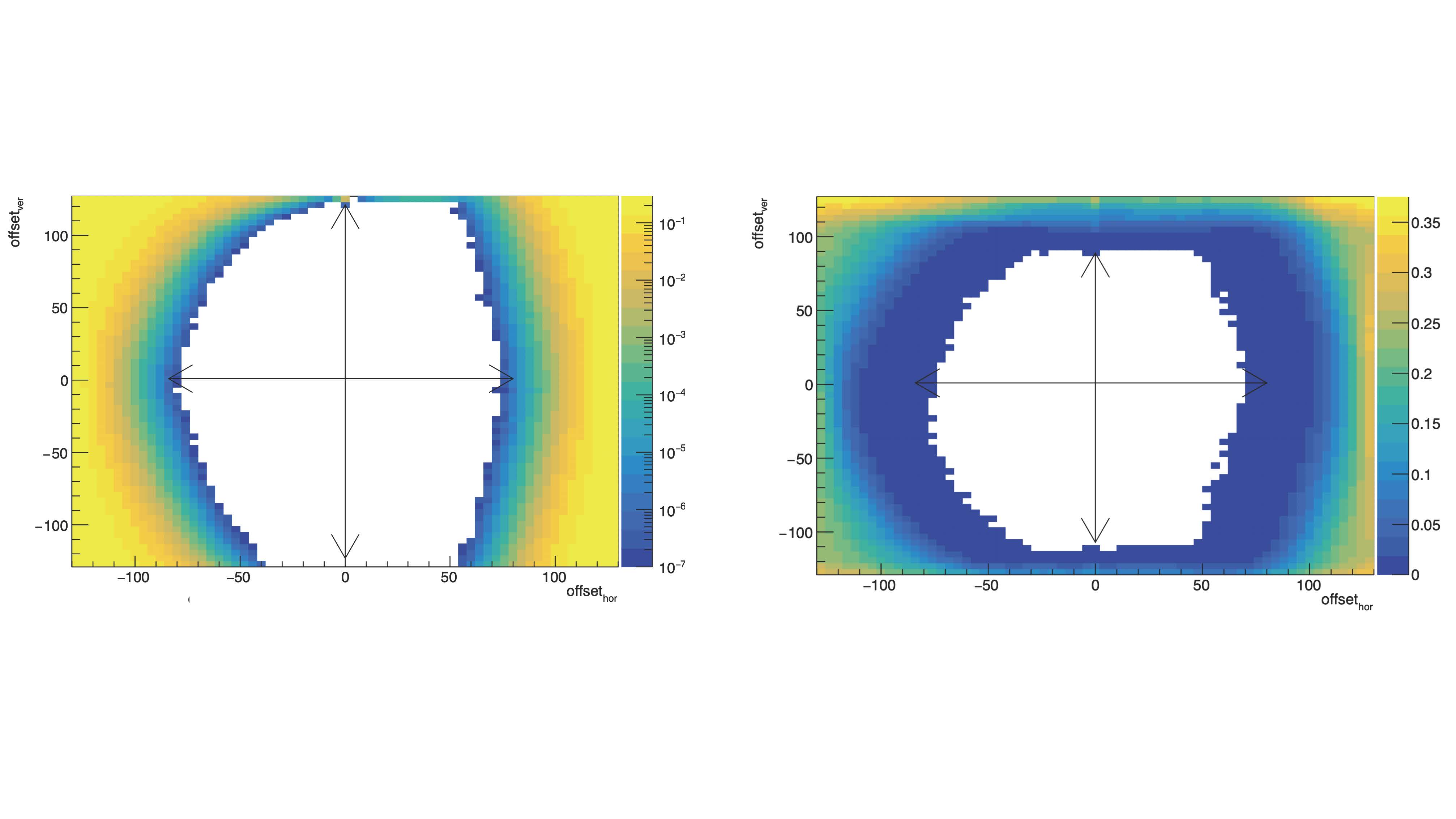
Figure 7 : Two examples of results from the qualification of a ladder in terms of the transmission quality of digitized data (test called "eye diagram"). The graphs show the dispersion in time (horizontal axis) and amplitude (vertical axis) in the transmission of digital signals at the speed of 1.2 Gb/s. The more open the diagram is (as in the figure on the left), the better the transmission quality will be.
(© Collaboration MFT)
The 500 ladders that equip the MFT detector are now all manufactured, tested and qualified. The development of the manufacturing and assembly processes and the associated quality control required more than two years of research by the Irfu team, in collaboration with teams from IN2P3. Two more years were necessary to finalize the production and qualification of all ladder. Despite the considerable difficulties associated with this state-of-the-art production, the rate of gold and silver qualified ladders remained around 91%, which is a real success for the project. This success is the result of the hard work of a high-performance, close-knit team, where technical and organizational difficulties have always been overcome in a spirit of collaboration, mutual trust, but also the pleasure of working together and friendship. The adventure continues for the MFT detector, now in the surface commissioning phase, but also for the "ladder team" which, with its experience, is already working on the development of new interconnection techniques between chips and FPCs, based in particular on laser soldering.
Contacts: Charlotte Riccio, Cyrille Vuillemin, Stefano Panebianco
• Innovation for detection systems › Detectors for both infinite physics Structure of nuclear matter › Quark-gluon plasma Technological platforms › Development and integration platform for nuclear and particle physics
• Institute of Research into the Fundamental Laws of the Universe • The Electronics, Detectors and Computing Division • The Nuclear Physics Division
![]() PHoCEA DSM 2024 - Tous droits réservés - Mentions légales - Ce site utilise Twitter Bootstrap
PHoCEA DSM 2024 - Tous droits réservés - Mentions légales - Ce site utilise Twitter Bootstrap
Dernière mise à jour : Feb 16th, 2024

