


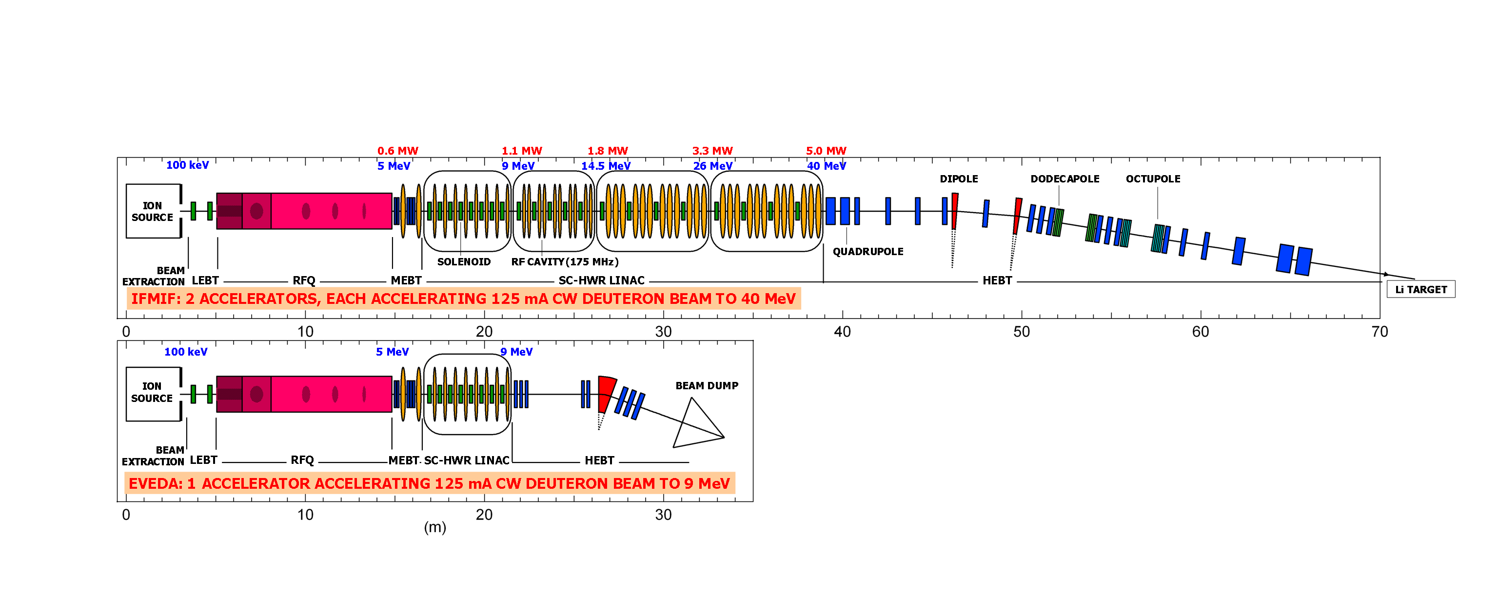
General layout of the IFMIF-EVEDA accelerators
A significant step has been taken in the design of the accelerators for IFMIF, the most powerful neutron source for the coming decade. Sophisticated numerical simulations have been used to demonstrate the ability to accelerate these intense beams in appropriate structures, as well as matching them between structures. The operations are extremely difficult because of the space-charge forces which threaten to disperse the beams. In this difficult context, specialists in beam dynamics from IRFU have established two decisive operations: the injection of ions from the source into the RFQ*, and then their injection into the superconducting HWR** linear accelerator . The complete model of the accelerator, from the source to the target, is the result of a European collaboration, which includes departments from CEA/IRFU in France, INFN-Legnaro in Italy, and CIEMAT-Madrid in Spain. IFMIF-EVEDA is a project within the Fusion Broader Approach in parallel to ITER, an agreement signed between Euratom and the Japanese government.
THE STAKES
These are the stakes of future fusion technologies. Materials surrounding the plasma in the fusion reactors of the future will necessarily be subject to a very intense neutron bombardment. Compared with existing reactors, the number of displacements of the atoms will be multiplied by several hundreds. The International Fusion Materials Irradiation Facility, IFMIF, project was launched to study the behaviour of materials in this severe radiative environment. Its goal is to reproduce an intense neutron flux, by bombarding a liquid Lithium target with a Deuteron beam. The IFMIF neutron source relies on a set of two accelerators. Each continuously accelerates 125 mA of Deuteron up to an energy of 40 MeV. The total power delivered to the target is 2 x 5 MW. This very high intensity and the required high beam qualities have necessitated the launch of a first phase, called EVEDA (Engineering Validation and Engineering Design Activity). The goal of this experimental phase is the study, in Europe, of a full-scale prototype accelerator (9 MeV, 1 MW), which will be installed at Rokkasho in Japan.
THE CHALLENGES and THE SOLUTIONS
The fundamental challenge for an intense beam is the preponderance of the defocusing space charge force. In the case of IFMIF this force attained up to five times the value of the focusing forces applied to the beam. Beam dynamics calculations become strongly non-linear and the coupling between the transverse and longitudinal planes becomes significant. Some particles become detached from the beam core, leading to the formation of a halo, which generates losses along the accelerator. Multi-particle numerical simulation remains the only method for studying the evolution of the beam in detail during its acceleration.
1. From the source to the RFQ
In the first sections of the accelerator, the major difficulty is to attain the large intensity of 125 mA required for the beam by minimising the losses, which can be significant at this stage. In order to allow the first accelerator element encountered, the Radio Frequency Quadrapole (RFQ), to transmit the maximum number of particles (the aim is to transmit more than 95%), the beam must be correctly extracted from the source, focused and then injected in the optimum manner. Optimisation of this beam transport line, required the development of a specific calculation code in order to obtain a space-charge potential map, which takes account of the compensation by the electrons of the residual gas. Some tens of calculations of the dynamics of charges in the plasma were needed, each having required a week of simulations on 50 processors working in parallel.
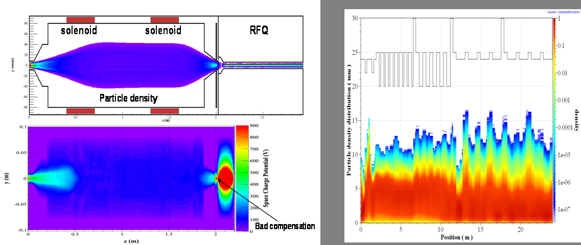
1st figure:
Above: Beam extracted from the source and injected into the RFQ
Below: Map of the space charge potential considering compensation by the electrons of the residual gas.
2nd figure:
Density of particles from 10-1 to 10-6 on the outer edge of the beam of the SC HWR-Linac, in the presence of standard errors accumulated on 200 machines.
2. From the RFQ to the superconducting linear accelerator:
At higher energies, losses generate additional heat dissipation in the cryogenic system and significant activation of the materials surrounding the accelerator. Considering the beam power, the maximum permissible losses correspond to just one particle in every 10 million! In order to minimise the formation of a halo and to control the trajectory of the peripheral particles of the beam, a beam transport line (called matching section) from the RFQ had to be carefully thought out. Global adjustment of the focussing and accelerating elements of the superconducting Linac have been optimised using the so-called Particle Swarm Optimization. This process is particularly suitable for non-linear functions with multiple minima. This remarkable result is maintained even in the presence of standard errors of fields or alignments.
Press contacts:
Phu-Anh-Phi NGHIEM (SIIEV),
Nicolas CHAUVIN (SACM)
Contributors:
O. Delferrière, R. Duperrier, A. Mosnier, D. Uriot, CEA/DSM/IRFU, Saclay, France
M.Comunian, INFN/LNL, Legnaro, Italy
C. Oliver, CIEMAT, Madrid, Spain
• pas de titre • Accelerators, Cryogenics and Magnetism Division (DACM) • The Systems Engineering Division
