

FAIR project Faraday cup and current transformer (ACCT)
Accelerator instrumentation refers to all the diagnostic instruments installed on the machine that emit signals indicating the operating status of the machine and that are also used to tune it.
These diagnostic devices are essential for starting up and operating an accelerator and require at least the following estimations and measurements:
? Beam current.
? Centroid position of the beam.
? Beam “quality” in terms of spatial distribution and energy.
? Purity of the particles making up the beam.
Several diagnostic devices are developed at SACM:
CURRENT
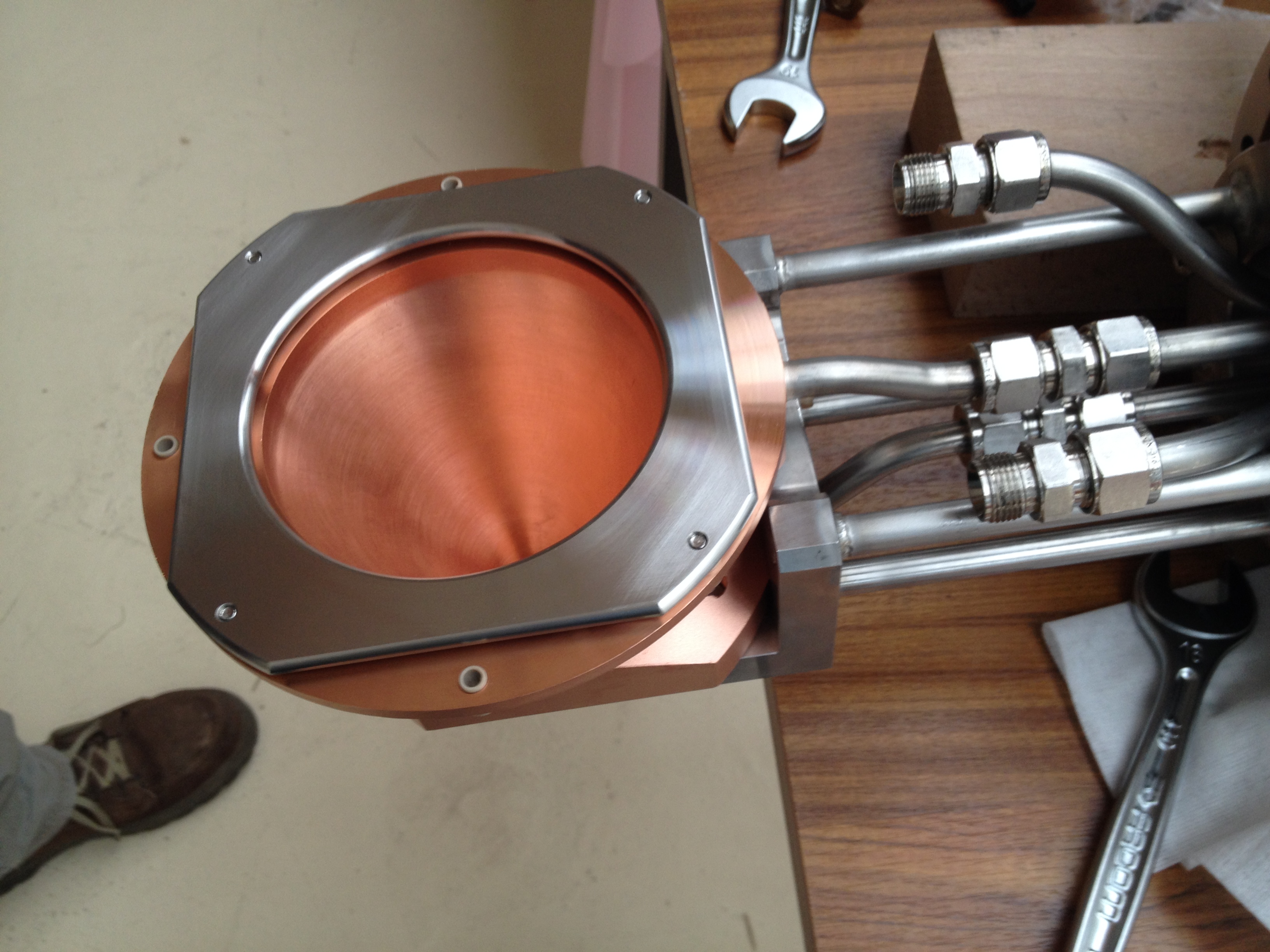
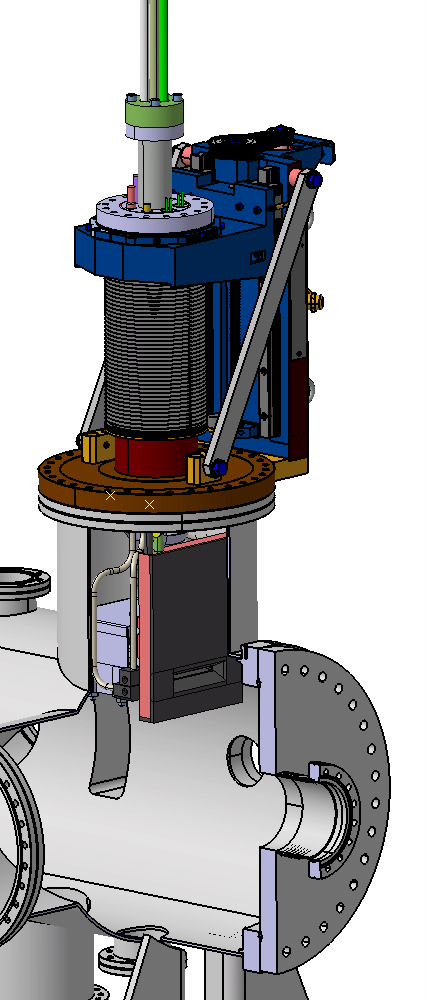
Beam current measurements essentially rely on the beam’s power density. The easiest way to measure the current is to intercept the beam with an electrically isolated cup and collect the beam charges. A Faraday cup was developed for the FAIR project to stop 200 W of average power and up to 8 kW of peak power.
Another method is to a use an AC current transformer - or ACCT - to obtain a non-interceptive measurement. This method uses magnetic flux for effective detection of current variations. This diagnostic feature is suitable for pulsed beams, as in the FAIR project. Magnetic induction, however, could be disturbed when the magnetic loop is immersed in a strong and constant magnetic flux, such as that generated by a solenoid leakage field. The performance of this equipment was tested on the IPHI low energy transport line, with the magnetic shielding of the turn optimized in terms of mechanical design.
Moniteur de position de faisceau installé dans un cryomodule E-XFEL
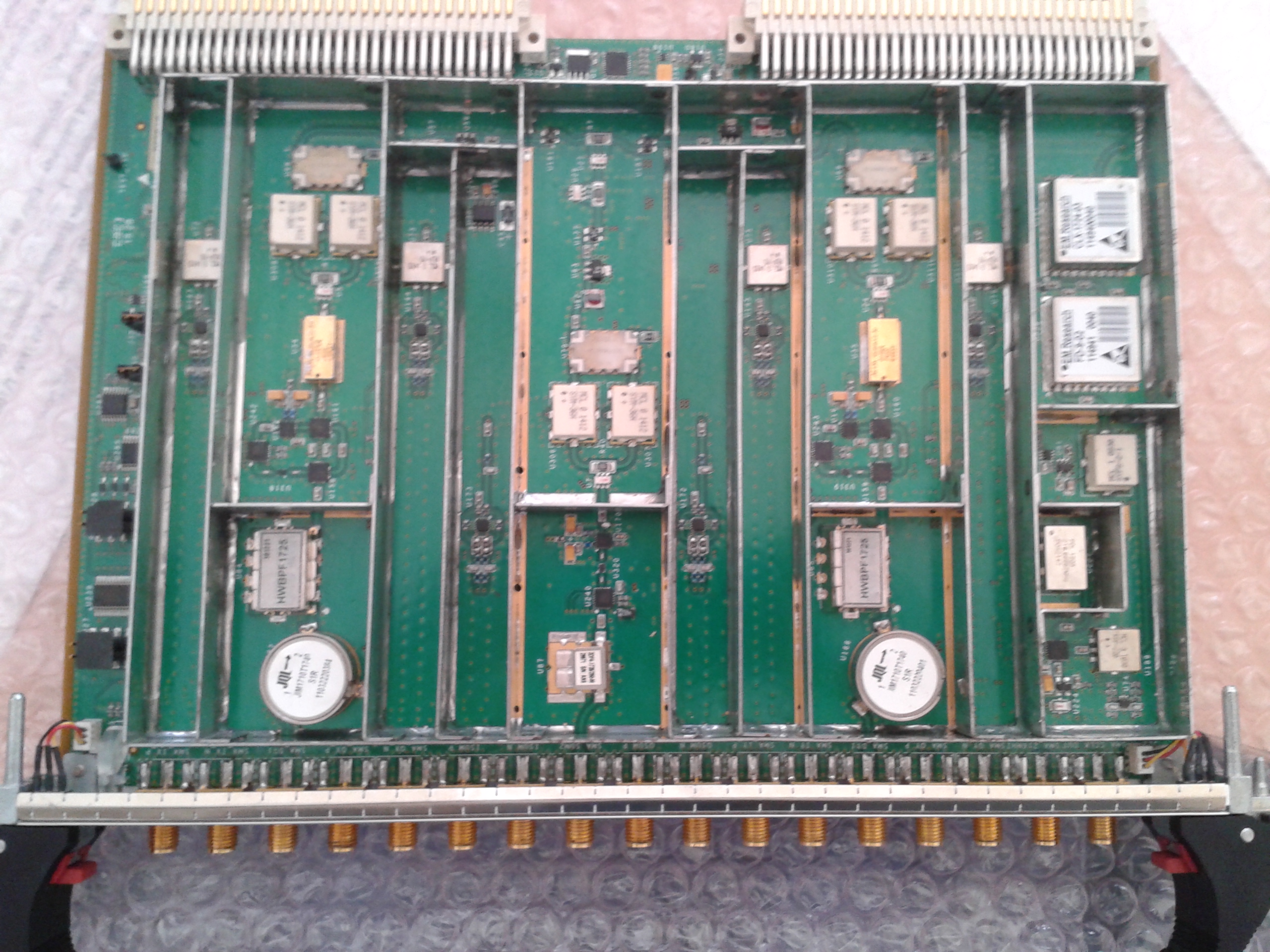
Signal processing electronics from the E-EXFEL BPM reentrant cavity
POSITION
Beam position monitors (BPMs) are non-destructive devices used to measure the beam position and current, and to check its transit time. Various BPM types are being developed.
? BPMs using radiofrequency cavities
The operating principle is as follows: when passing through the cavity, the beam excites electromagnetic modes that generate signals on four antennas installed at 90° around the beam pipe.
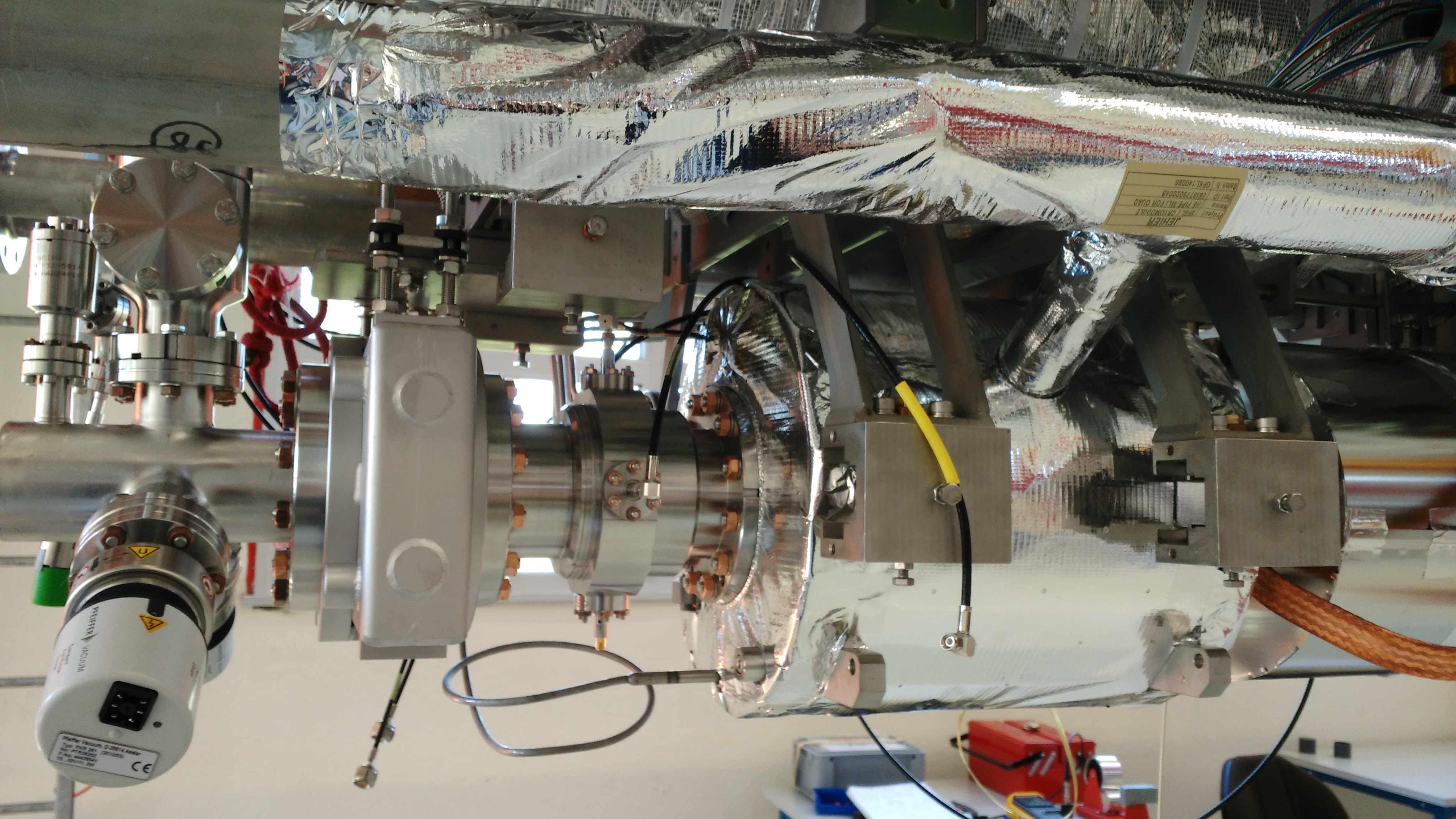
For the E-XFEL project, SACM is responsible for designing, manufacturing, and installing the cavity with its antennas, and its dedicated electronics for 31 position monitors, known as reentrant BPMs. These diagnostic devices are installed inside the linac cryomodules. The system electronics, which processes the signal from the cavity, is mounted on a printed circuit board and inserted into a rack that houses all the BPMs of the machine. This rack is developed by the Paul Scherrer Institute (PSI). A reentrant BPM installed in a 3.9 GHz cryomodule is already in operation on the injector. Another, installed in a hot section on the FLASH2 accelerator at DESY, was used during a series of measurement campaigns for the overall qualification of the system.
FAIR BPM installed on a test bench.
ESS emittance meter.
? BPMs using an electrostatic monitor
A monitor called button BPM, based on an electrostatic design, is also being developed. This device is composed of four button electrodes. The aim is to measure the charges induced by the electric field of the particle beam on an isolated metal plate. The closer the beam is to an electrode, the stronger the induced signal on that electrode. The current is determined by adding together the signals from the four electrodes. The difference between signals indicate the transverse positions on the X and Y axes. This type of monitor is developed in collaboration with GSI for the inter-tank section of the FAIR proton linac. Radiofrequency calculations led to the mechanical design of a prototype that was measured on a test bench designed and built by IRFU. A software is used to characterize sensitivity and linearity, obtain a position map, and determine the electrical center of the BPM. A two-channel preamplifier prototype was also produced and measured.
Another BPM, also based on an electrostatic design, is being studied for the SARAF project. It will be installed in the cryomodules and will operate at around 4 K.
QUALITY
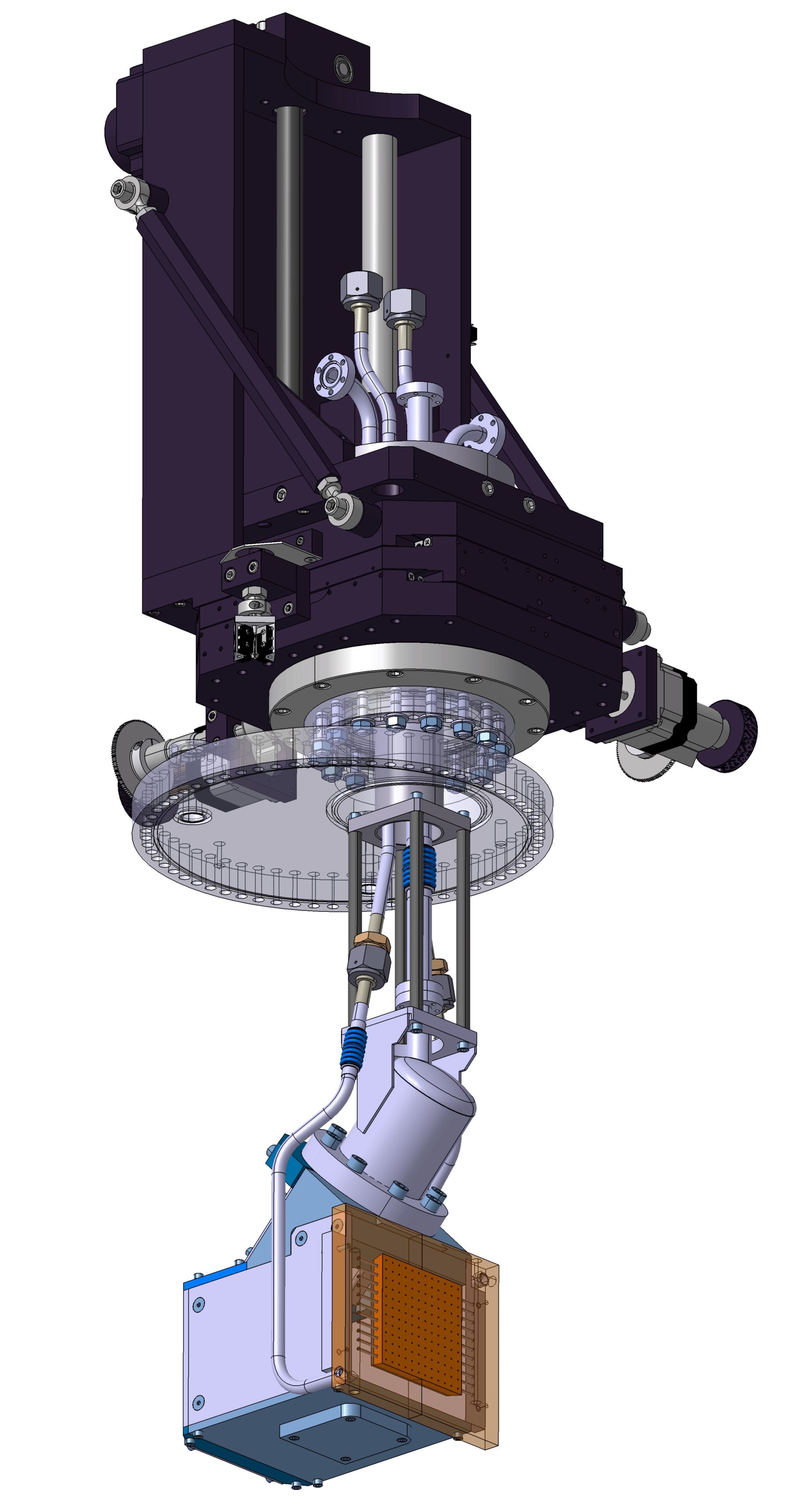
Beam quality is determined by an interceptive measurement by producing an emittance pattern, which shows beam intensity relative to its position x and its angle x’ in relation to the propagation axis z. Two measurement techniques are under development: the Allison scanner, and the 4D emittance meter, commonly known as the “pepperpot" emittance meter. An Allison scanner was chosen for the IFMIF project to relate the position x to the angle x’. For the ESS project, a second measurement is taken in the other plane, relating y to y’. This provides a true representation of the beam to see its evolution and, therefore, its “quality”.
The measurement principle is based on the electrostatic deflection of charged particles from the ion beam by a set of parallel, polarizable deflector plates. Beam quality is defined as the area of the ellipse in the phase space. This ellipse is obtained by measuring (x,x’), which represents beam current according to the position x of the selection slit, and the beam angle x’ selected by the slit.
The angle x’ is obtained by measuring the beam current according to the electric field E, created by the polarized plates, and the characteristics (charge, mass, and energy) of the beam particles.
One of the technical problems encountered when designing an Allison emittance scanner is the front slit, which is directly positioned into the incident beam to be qualified.
In the IFMIF project, where the deuterium beam transmits 15 kW continuous power, a tungsten tile, cleverly brazed on copper, and a suitable cooling system -ensures that the slit state is maintained despite the thermal expansion of materials.
As part of the ESS project, a pair of Allison scanners is being developed to withstand beam power of 750 W for a minimum task diameter of 6 mm (i.e. power density of 2.7 kW/cm²). Hot isostatic pressing of tungsten on copper for the beam dump blocks and the use of an exotic alloy (TZM) for the selection slits make it possible to withstand these values.
In the case of the MYRRHA linear accelerator, injector tuning is of the utmost importance, not only to ensure beam quality and minimize loss, but also because this accelerator-driven system (ADS) must ensure a very high level of reliability that has yet to be achieved by existing high-power accelerators. For this reason, diagnostics play a vital role in monitoring and understanding beam physics. Within this context, SACM has launched an ambitious R&D project to develop a 4D emittance meter, aimed at characterizing beam distribution in the four dimensions of the transverse phase space with unparalleled accuracy. Its development started with the French NEEDS program in 2013 and continues as part of the MYRTE program.

Results of proton proportion measurements at an energy of 50 keV obtained at Rokkasho in December 2015 and January 2016
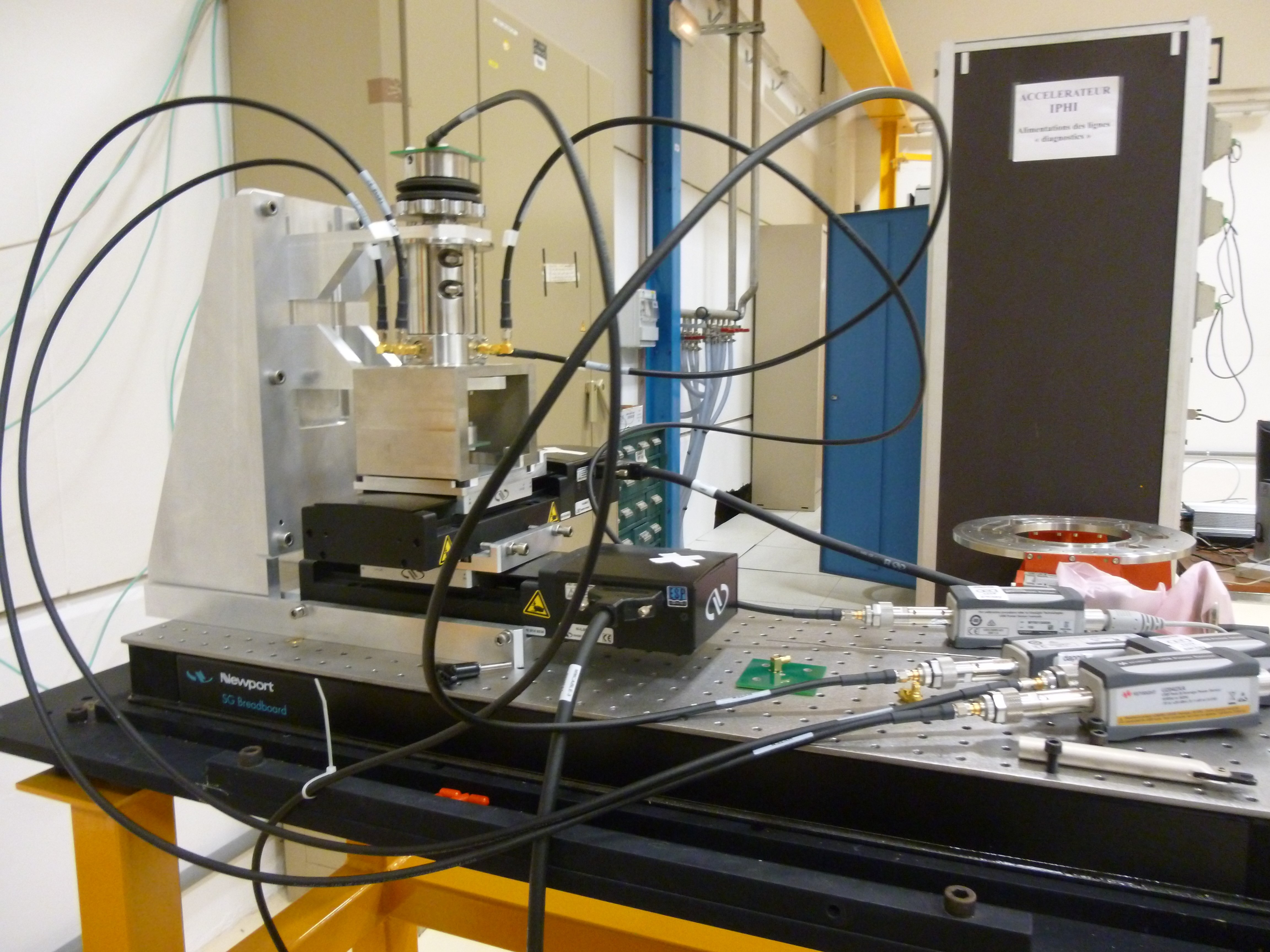
Low-energy 4D emittance meter currently in the final manufacturing phase. It is scheduled for beam testing in 2017.
This device features a beam dump drilled with 100 holes 70 µm in diameter, at 7 mm intervals, and arranged in tens. The 100 beamlets thus formed strike a light-emitting surface. Information is retrieved in a photograph taken with a triggered CCD camera. The choice of scintillator is one of the keys to the device. The pepperpot can move in both directions transverse to the beam between each photo for enhanced resolution. About a hundred such photographs are taken which, combined with suitable digital processing, can be used to identify beam emittance parameters. This measurement has the advantage of giving a result in both planes at the same time.
PURITY
Plasma tuning of the source can be optimized by estimating the proportions of the particle species making up the beam. The aim is to maximize the quantity of protons in the case of IPHI, for example, or deuterons in the case of IFMIF - in other words to optimize plasma purity. The other species present are considered as spurious. Expected purity values are in the region of 80%. These measurements are also used to monitor changes in plasma efficiency over time, as it has been demonstrated that deterioration of the boron nitride disks located in the source has a significant impact on plasma purity.
Two diagnostic devices based on completely different physical phenomena are used for these purity measurements.
? The first of these measures the intensity (number of photons) of the Hα line of the Ballmer series for atomic hydrogen, following a Doppler shift in the observation direction. This is a non-interceptive optical diagnostic device that is perfectly suited to high-current injectors. This type of device has already been developed for the IPHI and IFMIF injectors, and is currently being developed for ESS.
? The second is called a Wien filter. It measures the current (collection of charges) deposited on a Faraday cup for each species that has first been separated and selected by an electrostatic deflector in a magnetic field. This interceptive diagnostic device, which selects the beamlet through a 100 µm diameter hole, is well suited to short-cycle pulsed machines because of thermal problems. A Wien filter is currently being assembled in a Halbach magnetic configuration for the FAIR project proton linac.
• Physique et technologie des accélérateurs
• Le Département des accélérateurs, de cryogénie et de magnétisme (DACM)
• Laboratoire d’'études et de développements pour les accélérateurs (Léda)
• L'assemblage des cryomodules XFel • ESS : la source de spallation européenne • Xfel (Eurofel)
![]() PHoCEA DSM 2024 - Tous droits réservés - Mentions légales - Ce site utilise Twitter Bootstrap
PHoCEA DSM 2024 - Tous droits réservés - Mentions légales - Ce site utilise Twitter Bootstrap
Dernière mise à jour : Nov 19th, 2024

