

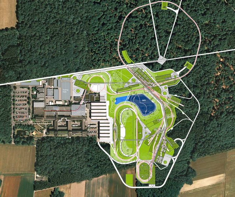
Aerial view of the FAIR site under construction
The Facility for Antiproton and Ion Research (FAIR) project conducted by GSI (Gesellschaft für Schwerionenforschung mbH) concentrates several areas of investigation in physics in a single facility: the physics of exotic nuclei, hadronic physics with proton and antiproton collisions, the study of relativistic heavy ion reactions (a few tens of GeV per nucleon), plasma physics and atomic physics.
THE PROTON LINAC
In the Franco-German agreement on participation in the construction of FAIR facilities, SACM’s contribution focuses mainly on the proton linear accelerator (the Proton Linac), which involves design and construction of an ion source, a Low-Energy Beam Transport line (LEBT), magnets for the High-Energy Beam Transport Line (HEBT) and the Beam Position Monitors (BPM).

Radiative emission of hydrogen plasma.
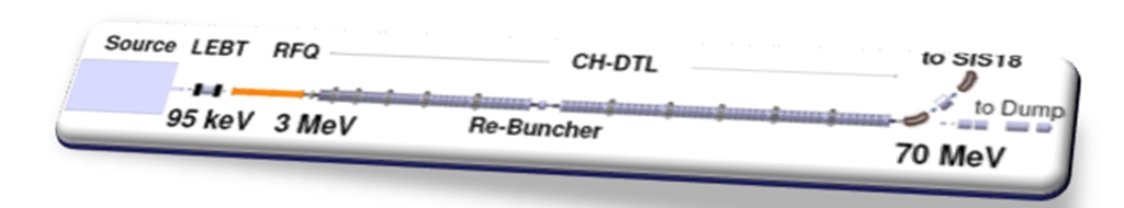
Schematic view of the proton linac.
The proton linac and associated components provided by SACM belong to the first stage of an accelerator facility capable of generating antiprotons by bombarding beams on a target.
It will accelerate a proton beam to an energy of 70 MeV. This linac consists of an Electron Cyclotron Resonance (ECR) proton source, followed by an LEBT line featuring two solenoid coils, a Radio Frequency Quadrupole (RFQ) and a Drift Tube Linac (DTL) based on Cross-bar H-mode (CH) cavities. The end of the accelerator features a set of magnets that steer the beam as it is injected into the upper stage: the SIS18 synchrotron. It consists of two dipoles set to a 45° angle and two quadrupoles.
The 35-mA beam required is pulsed at 4 Hz with a pulse length of 40 µs. While the beam current injected in the SIS18 is limited to 35 mA, the proton linac has been designed for a current of 70 mA.
Diagnostics equipment installed along the entire length of the accelerator is used to monitor the beam properties. In particular, a series of 14 BPMs is used to align the beam and measure intensity and energy along the linac.
Allison scanner
chambre chopper
Installation of the source assembly and LEBT line up to the exit of the second solenoid coil began at the end of 2012 with erection of the high-voltage cage and platform, followed by the cooling system. The entire system was placed under vacuum and high-voltage testing was completed. Platform energy was raised up to 100 kV.
At the beginning of November 2015, an important milestone was crossed when hydrogen plasma was generated for the first time in the ionization chamber, with 80 W of power injected by the magnetron, pulsed at 4 Hz. Since then, the beam diagnostics line has been in the assembly and test phase.
To measure beam intensity, two Alternative-Current Current Transformers (ACCT) were developed and installed in close cooperation with the manufacturer Bergoz. The first transformer is located at the exit of the source and the second at the exit of the second solenoid coil, before the chopper.
Working with IPHC in Strasbourg, SACM developed the Allison scanner to measure beam emittance, along with a Wien filter based on permanent magnets in a Halbach array to measure the different species (H+, H2+, and H3+) present in the beam.
GSI will provide a vertical and horizontal SEM-grid beam profiler (64 x 64 wires) and an adjustable slot-aperture to monitor beam size or limit beam intensity.

Wien filter.
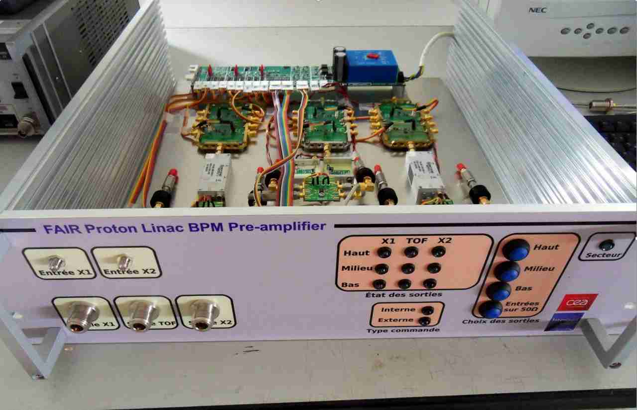
Prototype preamplifier.
INJECTOR COMMISSIONING
Scheduled to take place in three phases, commissioning began in 2015:
The additional diagnostics chamber is assembled at the exit of the accelerator tube for source characterization (intensity, proportions, and emittance).
The low-energy beam transport line is installed without the chopper chamber and the additional diagnostic chamber at the exit of the second solenoid coil is assembled. Diagnostics are to be installed in series between the two solenoid coils and after the second solenoid coil.
The chopper is installed and the additional diagnostic chamber is assembled after the chopper chamber. The complete Source and LEBT assembly is characterized.
Beam diagnostics: BPM
The series of 14 beam position monitors required along the accelerator tube include 4 BPMs located at the exit of the accelerating cavities, and 10 others located in the transport lines. Radiofrequency calculations and electromagnetic calculations were performed in cooperation with GSI. These operations took into account different energy values, different bunch lengths, different button and beam tube diameters and different button dimensions.
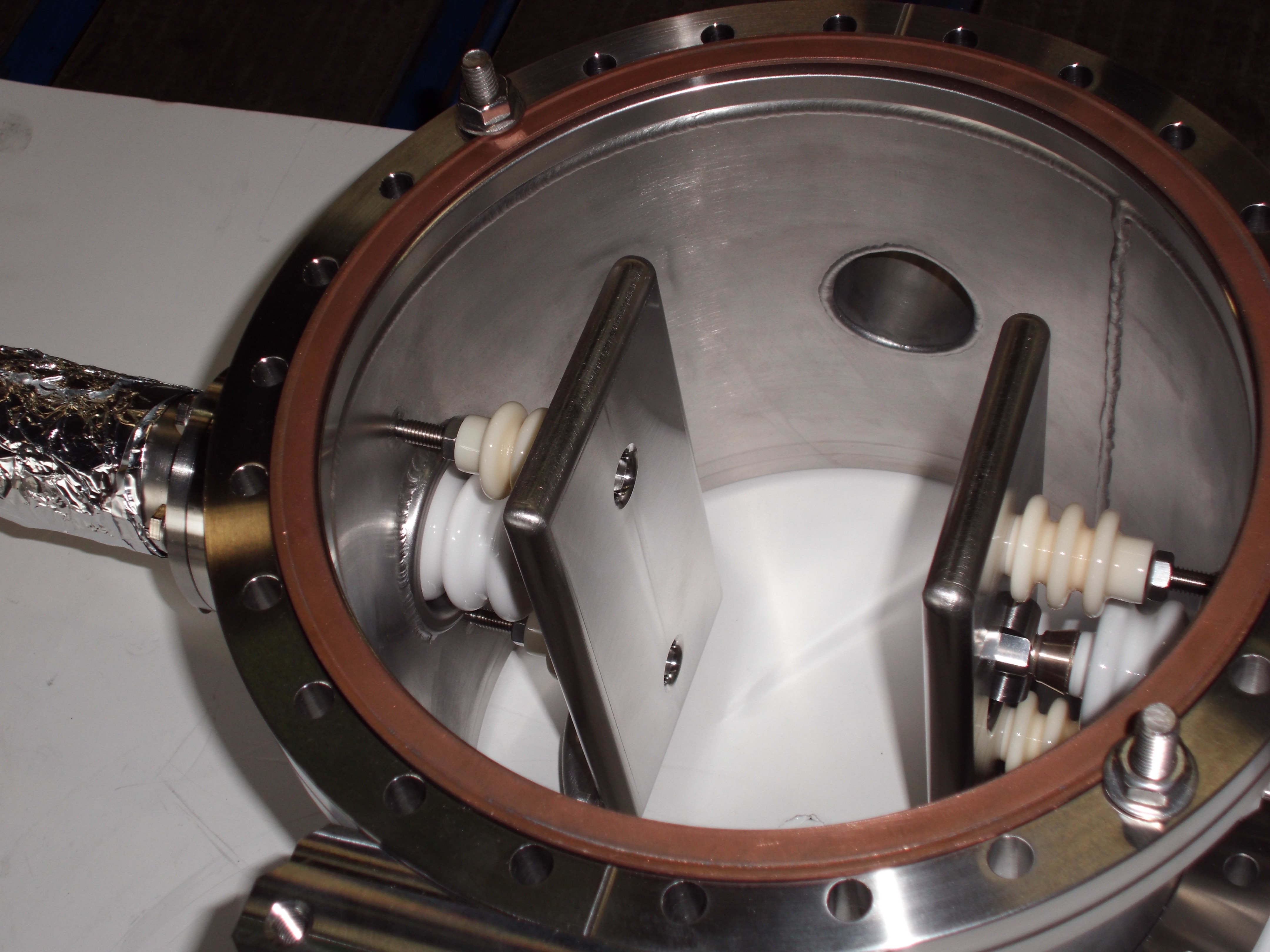
The design of the button BPM and the BPM body for the sections at the exit of the cavities gave way to mechanical construction of a prototype in 2015. The mechanical prototype consists of four 14-mm diameter button electrodes mounted on a cone-shaped tube used to reduce propagation of the electrical field generated by the cavity. A test bench designed and built by IRFU was used to measure and qualify this BPM.
A generator continuously sends a signal at a given frequency (either the accelerator operating frequency or one of its harmonic bands) on a wire passing through the BPM. This wire simulates the beam. For a given movement of the BPM, the power received by each electrode is measured by the power probes. Computer processing is used to characterize sensitivity and linearity, to map the position, and to determine the electrical center of the BPM. IPN Orsay (Institut de Physique Nucléaire d’Orsay) has also provided a test bench to perform and compare the different measurement results. A 2-channel preamplifier prototype was designed and built to amplify signals picked up by the buttons.
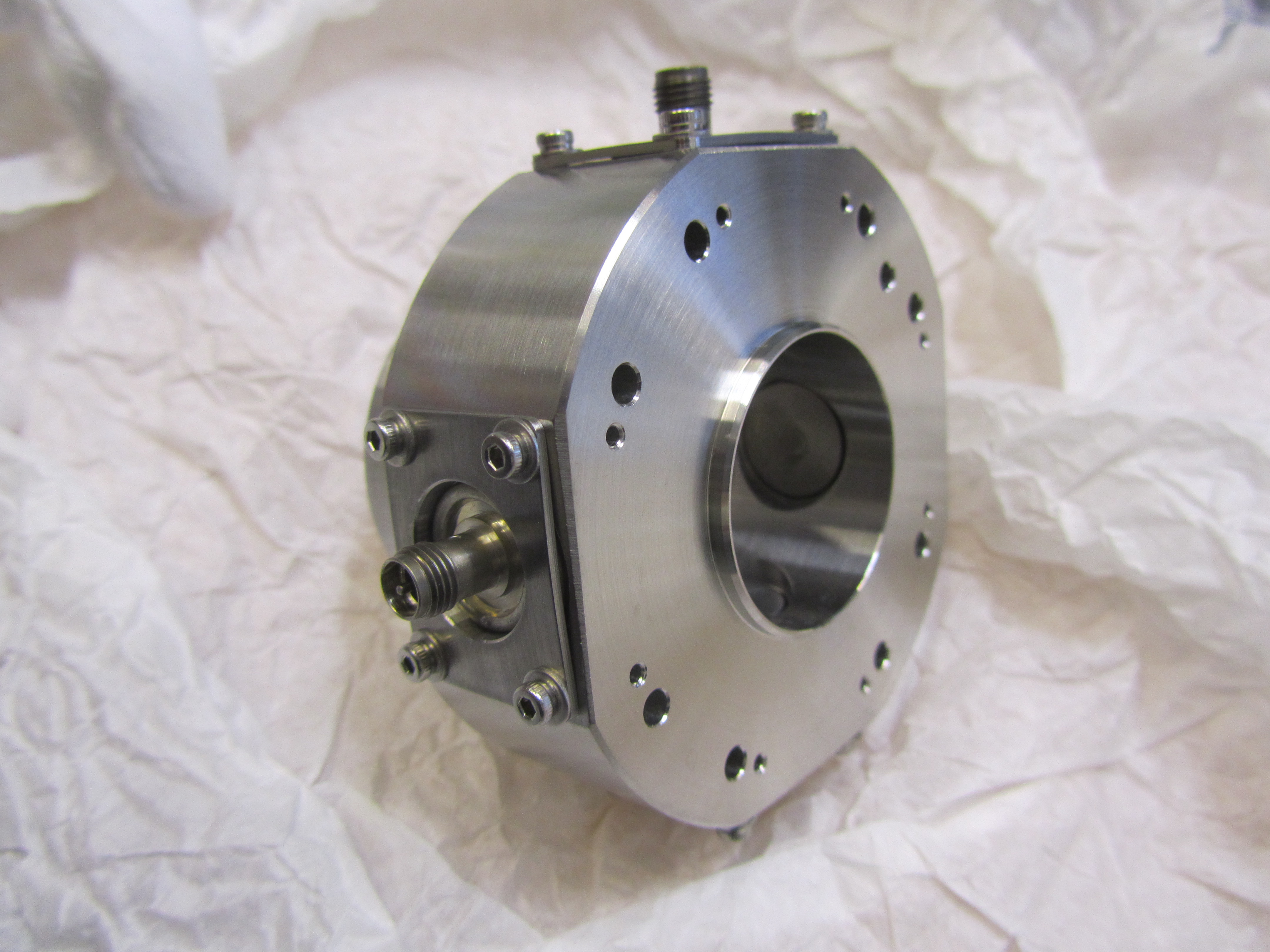
Inter-cavity section of BPM.
• Accelerator physics and technology › High-Intensity sources and injectors
![]() PHoCEA DSM 2024 - Tous droits réservés - Mentions légales - Ce site utilise Twitter Bootstrap
PHoCEA DSM 2024 - Tous droits réservés - Mentions légales - Ce site utilise Twitter Bootstrap
Dernière mise à jour : Nov 18th, 2024

