Investigation means
Technical Description
The goal of our program is to design and build a linear accelerator delivering a beam of approximately 200 MeV energy with remarkable qualities in order to measure and analyse the performances of the CLIC 12 GHz accelerating structures.
The corresponding experiments will be held in the new CERN CLEX building.
This setup needs to simultaneously reach its performances in terms of current (1.5 A in the macro-pulse), emittance (few pi.mm.mrad) and bunch length (sub-picosecond), in order to obtain a full scale simulation of the CLIC principal beam and test the 12 GHz accelerating structures.
Spécificities
The specifications beam are summarized in the following table:
Energy ~ 180 MeV
RMS normalized Emittance < 20 pi.mm.mrad
Energy Dispersion < 2%
Bunch charge 0.5 nC
Number of bunch Variable de 1-226
Inter-bunch distance 0.333 ns
RMS Bunch Length 0.75 ps
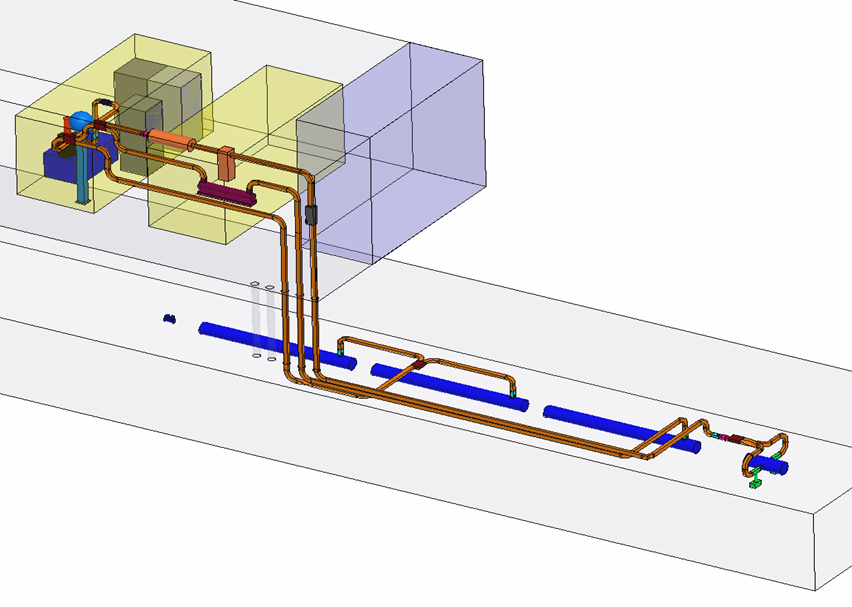
The accelerator includes (upstream to downstream): a photo-injector, a bunch compression section, followed of two accelerating sections and a transport line which leads to the CLIC 12 GHz sections, including the necessary beam diagnostics.
The CLIC/CTF3/CALIFES accelerator is composed of the following elements:
Injector
The purpose of the injector is to produce high charged bunches (0.5 nC) while maintaining very low transverse and longitudinal emittances. The gun photocathode will be started by laser.
Acceleration and bunch compression
Acceleration is carried out by means of 3 GHz sections operating in travelling wave mode. These sections, called LIL sections (LEP Injector Linacs) come from the old LEP (Large Electron Positron Storage Ring) injector.
These sections show quasi-constant gradient (thus at decreasing group velocity) and operate in 2pi/3 mode on a 4.5m length. By feeding them with a 25 MW RF power at the input, the average accelerating field will be about 17 MV/m, an energy gain of 76 MeV per section.
Radio Frequency System
The Radio Frequency system must provide power to the 3 sections (compression and acceleration), but also to the RF-gun cavity, and to the deflecting cavity at the beginning of operation.
The following table gives the power specifications for the different elements :
RF-GUN cavity 10 MW
Section 1 compression 20 MW
Sections 2-3 acceleration 2 x 25 MW
Deflecting cavity 6 MW