

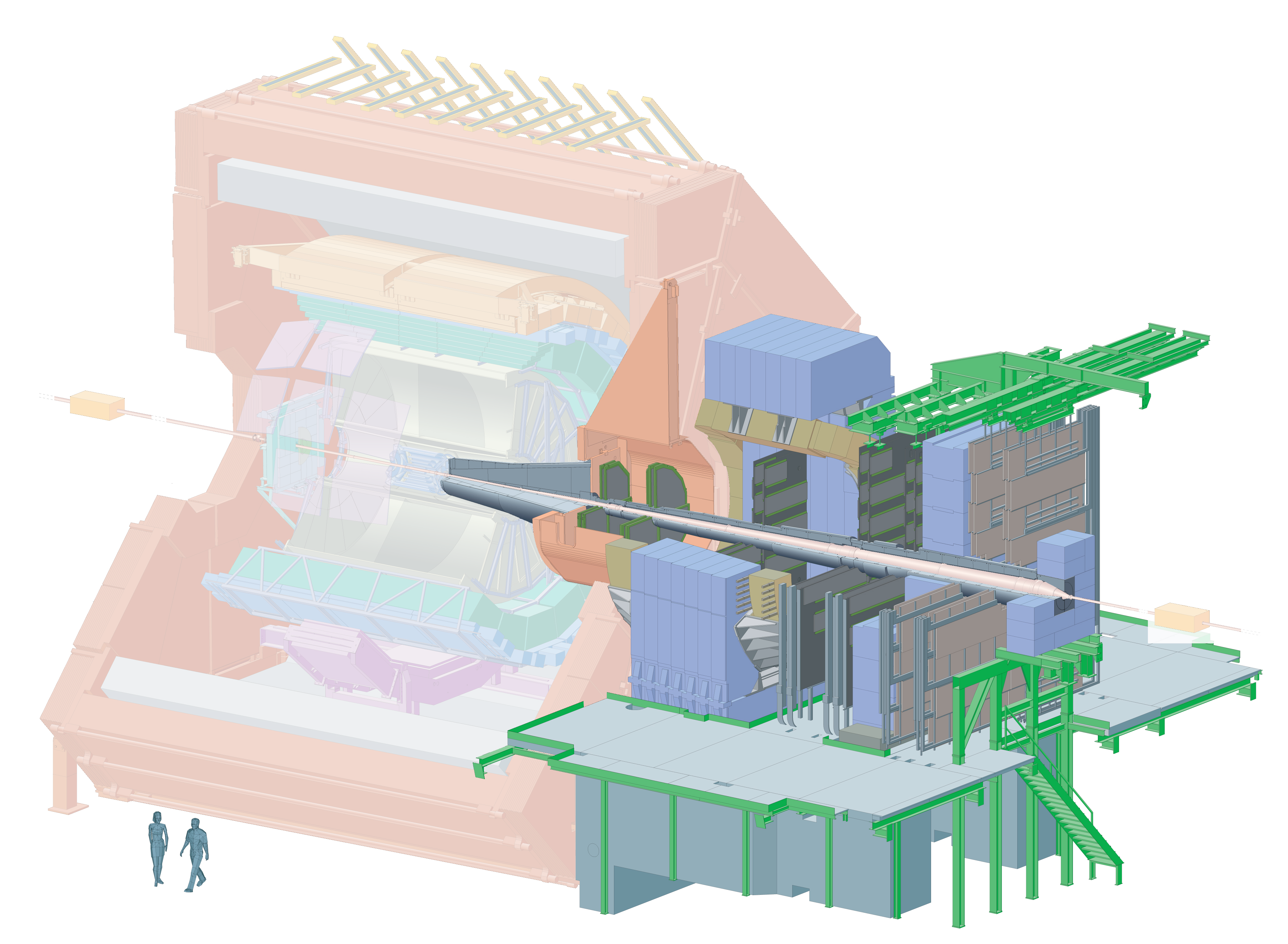
ALICE muon spectrometer
The IRFU contribution to the ALICE experiment focused on the largest tracking chambers of the muon spectrometer, which measures the μ+μ- pairs coming from the decay of the ϒ and J/ψ resonances.
The muon spectrometer, which covers the polar angular range between 2° and 9°, consists of a front absorber, five tracking stations with the third one located inside a warm dipole, an iron wall and triggering chambers. Each station consist of two cathode pad chambers with pads on both sides of the gas gap in order to get correlated x-y measurement in each chamber.
The tracking cathode pad chambers have different designs depending on their dimensions: the first two stations are made of quadrants whilst the largest chambers, with an outer diameter of up to 6 m, are made of modular detectors called “slats”, with an active area of 40 cm vertically along the wires times 80-240 cm horizontally. Each slat represents about 3% radiation length. Various sizes of the cathode pads are used in order to minimize the number of electronic channels when taking into account the decrease of the expected occupation toward large radii. The main characteristics of a slat have been validated in test beams at CERN. With an efficiency of 97%, a spatial resolution of 45 μm has been achieved in the vertical direction. These figures are well within the requirements of the dimuon arm. The construction of the 160 slats was shared between Cagliari, Gatchina, Nantes and Saclay laboratories, using same materials and assembly procedures. The construction spanned from end of 2003 to end of 2005. The Dapnia is also responsible for the slats supports, for the cooling and the integration of the tracking stations 3, 4 and 5. The slat supports are made of a honeycomb sandwich with carbon fiber skins. The use of carbon fiber ensures a good stiffness and a small thermal dilatation. The thickness of each of the 12 supports is smaller than 0.003 radiation length. The largest support is ~6 m high and ~3 m wide with a thickness of 18 mm and a planarity around 10 mm. The supports have been delivered in 2005.
Each half chamber, located on each side of the beam pipe, consists of slats mounted on one support along with services as cables and gas pipes. After two years of slat production, the chamber assembly phase gathers the slats coming from the four laboratories to test them, with high voltage, gas and final electronics read-out and mount them with the services on the support. This phase is running in an assembly hall at CERN at point 2 close to the ALICE pit, starting in spring 2006 and ending in summer 2007. Tools have been built for the handling of the supports, their hanging for mounting the slats, and the possibility to store them before their installation in the ALICE cavern. The rails on which are fixed the half-chambers allow stations 4 and 5 to be in close or open position compared to the beam pipe. The rail system of station 3 is complex and permits the delicate integration of the station inside the dipole. The SIS technical division in Dapnia designed these tools and rails. The rails were installed in fall 2006.
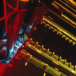
A side view of a tracking chamber.
Photo by A. Saba © 2007 CERN
The front end electronics cards (MANU cards) are plugged on the PCBs of these detectors, they consist of four MANAS chips (a preamplifier made in India) for the amplification and shaping of the analog signal, one MARC chip which controls the MANU card and makes the zero suppression and two 12 bits ADCs. We foresee to calibrate the electronics by sending a signal in situ via a calibration line. We expect a 2-3% calibration precision. Different tests have been done in order to check the whole calibration chain using the final hardware (electronics cards, readout programs, etc).
The pad position is known by construction and photogrammetry technics. First, pads are etched on PCBs (Printed Circuit Board) with an accuracy of few microns, then PCBs are assembled to form a slat with the help of a precise granite table (holes of 10 μm accuracy), finally the position of the slats compared to the supports is known by photogrammetry (~50 μm in plane and ~100 μm out of plane). The whole half-chamber is surveyed with an accuracy of 0.5-1 mm. As described previously, we took care of the material for the mechanical parts of the slats and the supports, using carbon fiber to minimize the thermal dilatation.
The installation of the cables has started in January 2007 and was followed by the commissioning phase running in parallel with the assembly and installation phases. The installation will end up in summer 2007 while the commissioning will last until the closure of the cavern. A complete test of the whole tracking system is foreseen well before the data taking.
After an intensive simulation done at Saclay, an air-cooling solution has been adopted, which is quite delicate especially for the third station located in the dipole. Ducts and pipes have been designed in cooperation with CERN groups and have been installed end of 2006. The integration of the chambers in the cavern is running in parallel with the assembly. The first half-chamber of station 4 was installed in July 2006; with the muon trigger chambers, it was the first detector to be in place. The quadrant installation has started in February 2007.
-five tracking stations;
-angular width: 2 to 9 degrees;
-Total detection area: nearly 90 m2 !
-The 3 tallest trajectography stations: stations 3, 4 et 5.
Total number of slats for Alice: 160
Number of slats produced in 2 years by the IRFU: 40
(November 2005: production ended)
![]() PHoCEA DSM 2024 - Tous droits réservés - Mentions légales - Ce site utilise Twitter Bootstrap
PHoCEA DSM 2024 - Tous droits réservés - Mentions légales - Ce site utilise Twitter Bootstrap
Dernière mise à jour : Nov 13th, 2024

